37
a.
Note
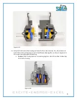
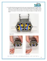
: In Figure 4.26, there is an
open
area where you can see all the gears. If you see a
grey horizontal shaft going through this area, you have mated the center housing
backwards.
Figure 4.25
Figure 4.26
19.
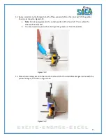
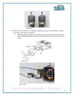
After ensuring that the gearbox housing parts are mated correctly, locate and insert three
17mm self-tapping screws to hold the assembly together, as shown in Figure 4.27. The screws
should be tightened and snug.
a.
Note
: There are 4 holes, but only 3 screws inserted. The front lower hole is for
alignment only. Inserting a screw into this location will damage the housing.
b.
Caution
: Do no over-tighten the screws!
Figure 4.27
20.
Congrats, the right side of your gear housing is now finished!
21.
Repeat steps 2 – 18 for the left side of the housing. The completed left side of the gear assembly
is shown in Figure 4.28.
Содержание Pi-Bot v2.00
Страница 67: ...67 Figure 6 15 ...
Страница 78: ...78 UltraSonicSensorTestwithLED Program ...
Страница 80: ...80 ObstacleAvoidance Program ...
Страница 82: ...82 ObstacleAvoidancewithLED Program ...
Страница 83: ...83 ObstacleAvoidancewithLED Program CONTINUED ...
Страница 90: ...90 Download and run the following program LineFollowing Program ...
Страница 91: ...91 LineFollowing Program CONTINUED ...
Страница 94: ...94 AdvancedLineFollowing Program CONTINUED ...
Страница 95: ...95 AdvancedLineFollowing Program CONTINUED ...
Страница 96: ...96 AdvancedLineFollowing Program CONTINUED ...
Страница 110: ...Appendix B Complete Pi Bot Wiring Schematic ...


