


6934900000
17
- The red Led
(2)
switches off
- When the yellow Led
(4)
is off it means that the
THOR working temperature is within normal
values.
- With the TEST GAS button
(3)
check that the
pressure of the compressed air has been correctly
set.
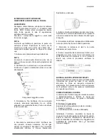
- Connect the positive cable (Earth Clamp)
firmly to
the piece to be cut. (N.B.: do not attach the clamp
to the part of material that will be cut off).
- The Inverter is now ready for work. When you
want to start, position the torch on the work-piece
to be cut and press the button on the torch.
- Now the arc is transferred to the work-piece to be
cut. Move the torch in the desired direction at a
speed that ensures a good cutting quality.
-When the cut is finished, release the torch button
to stop the arc; air will continue to flow out for 15
seconds to cool the torch parts.
CUTTING:
-Do not freely or unnecessarily ignite the pilot arc
when not cutting! This action considerably
reduces the life of the nozzle.
-Start cutting from the edge of the work- piece, until
you manage a perforation.
-Ensure that, during cutting, the sparks fall away
from the bottom of the work-piece. If sparks or
dross come out at the top it means that the torch is
being moved too fast or that there is not the
necessary power to perforate the work-piece.
-Keep the torch in a vertical position and observe
the arc along the cutting line. By dragging the torch
lightly on the work-piece you can keep the cut
regular.
-When cutting thin materials, reduce the power to
give optimum cutting quality.
PIERCING:
- Hold the torch at a distance of approximately 1
mm. from the work-piece before pressing the torch
button. This distance will prolong the life of the
nozzle and other parts.
- Start cutting at a slight angle rather than with the
torch in a vertical position. This allows the molten
material to come out at one side instead of spitting
back towards the nozzle, thus protecting the
operator against sparks and increasing the life of
the nozzle.
- Hold the torch facing away from your body and
bring it slowly into the vertical position. (This is
important when cutting thick gauges). Ensure that
the torch is pointed away from you and from
anyone else in the vicinity, to avoid damage
caused by sparks of molten metal.
- When the pierced hole has been completed,
carry on with cutting.
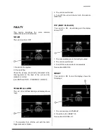
COMMON MALFUNCTIONS DURING CUTTING:
The work-piece is not completely perforated.
The causes may be:
−
The current is too low.
−
The cutting speed is too fast.
−
The torch components are worn.
−
Incorrect torch angle
- The piece to be cut is too thick.
Presence of waste material on the bottom of the
cut.
The causes may be:
−
The cutting speed is too low
−
Insufficient cutting current
−
Incorrect torch angle
−
The cutting current is too high
−
Torch components are worn.
−
Travel speed is too slow
CONTACT CUTTING
This type of cut is used for materials with thickness
5mm or less.
- Remove the spacer and the 60A TIP. Prepare the
torch, fitting the consumable parts for contact
cutting: Tip 40A and Deflector.
- Regulate the current from minimum up to 40A
(max).
- Make the cut, remaining in contact with the work-
piece to be cut.
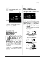
SWITCHING OFF
After having made the cut, the operator may switch
off the machine as follows
:
1-
Switch off the
machine
turning the
line switch
(9)
to
position “0“.
2-
Check that the
machine live Led (6)
and the
air
presence Led (1)
are off.
3-
Disconnect the
plug
of the machine from the
power socket
.
4-
Disconnect the cable from the connector (earth
clamp).
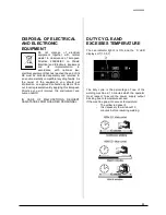
CLEANING THE INSIDE OF THE MACHINE:
ALWAYS
DISCONNECT
INPUT
PRIMARY
SUPPLY!!!
Before cleaning the inside of the machine it is
obligatory to
FIRST
follow the
WARNINGS
described above and to proceed as follows:
1- Remove the casing, slackening the side screws;
2- Remove all traces of dust from the internal parts
of the machine by means of a jet of compressed
air at a pressure no higher than 3 Kg/cm
2
;
3- Visually check all the electrical connections,
ensuring that the screws and nuts
are well
secured;
4- Visually check the state of all the components:
replace any deteriorated components;
5- Put back the casing, tightening the side screws
.
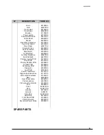
Deflector cod 6074400000
Tip 40A cod 6073800000
Содержание THOR 123
Страница 23: ...6934900000 23 WIRING DIAGRAM THOR 123...
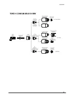
Страница 25: ...6934900000 25 TORCH CONSUMABLES VIEW...
Страница 29: ...6934900000 29 Info www stelgroup it tel 39 0444 639525...


