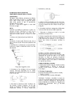
Stel THOR 123 Скачать руководство пользователя страница 16


6934900000 


16


LIFTING  

WARNING

THOR 123  peso 50kg / 110lbs 


Lifting by hand: 

Lift the machine using the two handles provided


Lifting with hoist and strap 

Lift  the  machine  by  using  ONLY  both  handles  as 
shown on the picture. 
Keep the machine as horizontal as possible 


INSTRUCTION FOR 
INSECURE POSITIONING 

Failure  to  properly  secure  the  machine  can  cause 
personal injury. 
If machine is in an insecure position do not attempt 
to switch on. 
Do  not  put  the  machine  on  an  unlevelled  surface 
greater than 10°. 


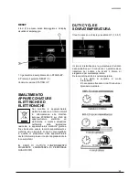
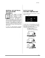
FRONT PANEL DESCRIPTION 
- THOR 123 


Air presence led 

Protection alarm led 

Air test button    

Excess temperature led  

Enable cutting led 

Machine live led 

Current display 

RESET button  

9  

ON-OFF switch 

10 

Cutting current regulation 


STARTING UP 

The  operator  may  start  up  the  machine  only  after 
having  read  and  understood  all  parts  of  this 
manual.


Depending  on  the  type  of  cut  to  be 

performed  he  must  follow  the  work  phases 
described below. 

1- 

Ensure  that  the  work  environment  and  your 

clothing satisfy the safety requirements described. 

2- 

Position the Inverter in a place where there is no 

obstruction to air circulation. 

3- 

Connect  the  THOR  to  a  suitable  power  socket 

(an earthed socket is obligatory). 

4

- Connect the compressed air pipe to the air filter 

on the rear panel. 

5- 

Ensure  that  there  is  no  water  in  the  filter.  If 

necessary, empty the filter. 
 

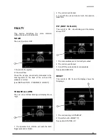
For the instructions below, refer to the details :


-  With  the  potentiometer  for  regulating  the  output 
current 

(10)

,  set  a  suitable value for  the  thickness 

that  is  to  be  cut,  in  agreement  with  the  line 
capacity.  
- Turn the switch on the front panel 

(9)

-  the green led 

(6)

 will light up (machine live). 

-  the  green  led 

(1)

  will  light  up  to  indicate  the 

presence of compressed air in the air circuit. 

- The red Led


(2)


is illuminated. 


ATTENTION press the RESET button (8) 

Содержание THOR 123

Страница 1: ...6934900000 1 MANUALE DI ISTRUZIONE PER TAGLIO PLASMA INSTRUCTION MANUAL FOR PLASMA CUTTING MACHINE THOR 123 THOR 123 THOR 123 THOR 123 Info www stelgroup it tel 39 0444 639525...

Страница 2: ...ww stelgroup it The following harmonized standard in force within the EEA has been used in the design EN 60974 1 ed 4 Arc welding equipment Part 1 Welding power sources EN 60974 10 ed 2 Arc welding eq...

Страница 3: ...ficiente usare un aspiratore che aspiri dal basso IL CALORE GLI SCHIZZI DEL METALLO FUSO E LE SCINTILLE POSSONO PROVOCARE INCENDI Non saldare vicino a materiali infiammabili Evitare di portare con s q...

Страница 4: ...ratore necessita di aria compressa L aria usata dovr essere priva di impurit olio acqua od altri prodotti inquinanti RICEVIMENTO L imballo contiene N 1 generatore N 1 manuale istruzione N 1 cavo massa...

Страница 5: ...un adeguato interruttore munito di fusibili ritardati MESSA A TERRA Per la protezione degli utenti il generatore dovr essere assolutamente collegato correttamente all impianto di terra NORMATIVE INTER...

Страница 6: ...oder regolazione corrente MESSA IN OPERA L operatore addetto durante l utilizzo della macchina deve obbligatoriamente porsi nel lato anteriore della stessa onde evitare che i fumi prodotti dal taglio...

Страница 7: ...taglio MALFUNZIONAMENTI COMUNI DURANTE IL TAGLIO Il pezzo non completamente forato Le cause possono essere La corrente troppo bassa La velocit di taglio troppo alta I componenti della torcia sono con...

Страница 8: ...ate o altre come vetro plastica e metallo MANUTENZIONE DELLA TORCIA A Pulizia della torcia Anche se si adottano precauzioni per utilizzare soltanto aria pulita con la torcia possibile che all interno...

Страница 9: ...la ove del caso 5 Estrarre l elettrodo direttamente dal corpo torcia Verificare che la faccia dell elettrodo non presenti un usura eccessiva facendo riferimento alle figure di seguito 6 Rimontare l el...

Страница 10: ...ssivamente 3 Protezione sicurezza torcia o malfunzionamento dell interruttore della torcia a Verificare che la shield cup sia montata correttamente b Controllare la continuit dell interruttore nell im...

Страница 11: ...servare se presente una formazione di olio o umidit non azionare la torcia DIFETTI In questa sezione vengono descritti I pi comuni malfunzionamenti e come vengono indicati MANCANZA ARIA Il led 1 di pr...

Страница 12: ...unte a fine vita devono essere raccolte separatamente e conferite ad un impianto di riciclo ecocompatibile In qualit di proprietario delle apparecchiature dovr informarsi presso il nostro rappresentan...

Страница 13: ...OF ELECTRIC SHOCKS Take the following precautions when working with a welding machine keep yourself and your clothes clean do not be in contact with damp or wet parts when working with the welding mac...

Страница 14: ...ust be free from impurities oil or other polluting substances DELIVERY OF THE MATERIAL The package contains N 1 Inverter N 1 instructions manual N 1 torch N 1 earth cable N 1 air connection Check that...

Страница 15: ...pe fuse s In the event of damage to the power cable replacement or repair must be performed by a qualified person at an approved service centre EARTHING To ensure user protection the Inverter must by...

Страница 16: ...er having read and understood all parts of this manual Depending on the type of cut to be performed he must follow the work phases described below 1 Ensure that the work environment and your clothing...

Страница 17: ...the torch facing away from your body and bring it slowly into the vertical position This is important when cutting thick gauges Ensure that the torch is pointed away from you and from anyone else in t...

Страница 18: ...NNECT INPUT PRIMARY SUPPLY Disconnect primary power at the source before disassembling of torch leads Frequently review the important safety precautions at the front of this Manual Be sure the operato...

Страница 19: ...ge Check for excessive wear plugged gas holes or discolouration Check the lower end fittings for free motion Replace if necessary 5 Pull the electrode straight out of the torch head Check the face of...

Страница 20: ...nspect torch assemblies and replace if necessary 5 faulty components in the system a return for repair or have qualified technician repair as per service manual C limited output with no control 1 poor...

Страница 21: ...ON fast blinking and display shows TRI 1 The operator Turn ON the unit with the torch trigger pressed or broken 2 The unit is now blocked 3 Turn Off the unit and check torch See section SERVICE PIP P...

Страница 22: ...t you should get information on approved collection systems from our local representative By applying this European Directive you will improve the environment and human health IN CASE OF MALFUNCTIONS...

Страница 23: ...6934900000 23 WIRING DIAGRAM THOR 123...

Страница 24: ...Right output inductance Left output inductance Base Input Power cable Flat connection Flat connection Isolator Foot Cover Door Handle Cerniera Side Grid Data Plate Front Panel PCB Pilot Arc Switch Se...

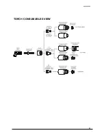
Страница 25: ...6934900000 25 TORCH CONSUMABLES VIEW...

Страница 26: ...Gouging 9 8241 Stand off Guide 9 8281 Deflector 9 8243 Start Cartridge 9 8213 Torch Head 9 8219 1Torch 6m SL60 7 5253 1Torch 6m SL100 7 5254 601048000L 607380000L 601238000L 607390000L 607400000L 609...

Страница 27: ...the Shield Cup with the torch tip in direct contact with the work up to 60 Amps Standoff Cutting The preferred method of cutting metal thicker than 1 4 6 mm and at current levels above 60 Amps Provide...

Страница 28: ...d for cutting light gauge sheet metal Gouging A simple method of metal removal by angling the torch to a lead angle of 35 45 and using a gouging tip While maintaining a constant standoff distance this...

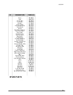
Страница 29: ...6934900000 29 Info www stelgroup it tel 39 0444 639525...

Отзывы: