However, there are some double errors that may lead to the destruction of the System-Manager or components
(consumer components, modules ), such as:
•
reverse polarity battery connection on the solar PV terminals
•
One battery wire on the module terminal, the other on the load terminal.
•
A wrong voltage source (grid current with 230VAC ) on the solar PV terminals
6.7 Grounding
By grounding the negative poles of the loads, battery and modules together, the electronic components that are
necessary for the regulation and the safety fuse are bypassed. In this way, internal protection components are also
deactivated and the System-Manager can be destroyed, as well as damage to the PV system may occur.
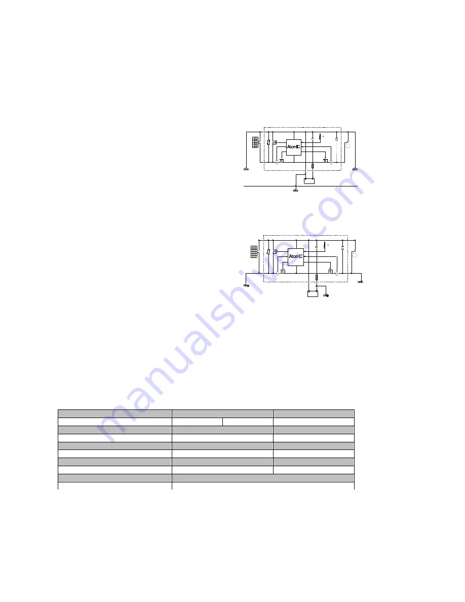
6.7.1 Positive Grounding
The following passages describe some of the technical
possibilities of
a po grounding scheme. The aim is to always
maintain the
System-Manager's proper functions and still achieve
grounding to
all the main components. National regulations of the
operational
area must be adhered to by the installing electrician. Loss of
the “safety
low voltage status” arising from grounding has to be
compensated
by corresponding insulation methods of active parts
(protection
against direct contact).
A+
A-
L-
L+
M+
M-
When grounding at the plus-side is done, it can also be considered as common ground for all system components. All
plus connections are internally connected anyway in the System-Manager.
6.7.2 Negative Grounding
If Negative Grounding is used, only one minus connection
from any
one the components, i.e. module, battery or load can be
grounded.
When your solar system requires a minus ground (e. g.
battery
minus), only this component can be connected to ground. A
connection
with further minus poles (module or load) bypasses the
control
elements and the fuse. This can lead to a malfunction and
destruction
of the System-Manager.
A+
A-
L-
L+
M+
M-
In systems with required load-minus-grounding (e.g.
grounding
of aerials), all further components have to be connected with the grounds floating.
7 Maintenance
The System-Manager depends on its heat sink’s cooling area to meet its technical specifications. Therefore, the heat sink
must be kept clean of dust and debris that hampers cooling efficiency.
As far as the fuse and the cables are concerned, they must be checked for corrosion periodically. Due to corrosion, the
transfer resistance increases and the contacts could become so hot that damage occurs.
8 Technical Data
8.1 Performance Data
Reglertyp
2401
4401
System voltage
12V
24V
48V
Max. input voltage
48V
90V
Nominal load current at 20°C
40A
40A
Nominal discharge current at 20°C
10A
10A
max. current for 10s
55A
55A
Surge current for 0,5s
60A
60A
max. pulse current (200ms)
180A
180A
Own consumption
14 mA
Temp. range during operation
-25°C...50°C
System-Manager TAROM | 716148
page 14
V09_45A


