AUTO BLOWDOWN AND AUTO ON/OFF TIMECLOCKS
The “HC” steam generator, with an optional auto blowdown sys-
tem, will automatically purge the steam boiler. Working in con-
junction, the Time Clock and electrically motorized valve, which
allows blowdown on boilers, prevents excessive mineral and scale
build-up.
IV.
A. Installation
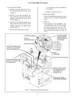
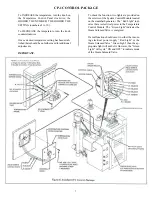
1. Auto Blowdown Drain Valve (plumbing)
Attach the main blowdown drain valve to 3/4" indirect drain
(most local codes require a blowdown tank). A strainer must
not be used with the valve. Note: the drain line must be angled
downward, allowing gravity to properly drain the machine.
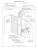
2. Auto Blowdown (electrical)
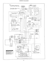
All wiring is done at the factory so that no special electrical
wiring is necessary.
B. Operation
First decide the TIME OF DAY you require the boiler to
blowdown. It is recommended to select a time while the boiler
is in use, but under low demand. For best results program the
Timer to blowdown every day of use for a period of 5 minutes.
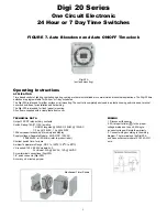
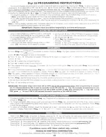
The blowdown will begin with the Timer “ON” command and
end with the Timer “OFF” command. See Page 9 and 10.
C. SETTING AUTOMATIC ON/OFF TIME CLOCK
The Steam Generator will turn ON with the Timer “ON” com-
mand and OFF with the timer “OFF” command. See Page 9
and 10.
IMPORTANT. The Auto Blowdown Timer and Auto On/Off
Timer are two separate timers. If your steam generator only
has one timer, then only one of these two options can be pro-
grammed. Check with the installer to see which option has
been purchased.
V. STEAM GENERATOR OPERATION
A. Place START, WATER SOLENOID, and STEAM SOLE-
NOID switches in the ON position. The Water Solenoid Valve
will open and the boiler will fill to its proper level (one-half to
two-thirds of the sight glass full) and automatically shut-off.
B. When there is adequate water in the boiler the power contactor
will energize and the red power light will illuminate indicating
that the boiler is heating up.
NOTE:
This boiler is equipped with a Solid State Liquid Level
Control System. Water level is maintained in the boiler, by a
ground potential signal between each stainless steel water level
probe and the boiler, and operates by sensing the electrical resis-
tance of water.
Both the water feed and low water cut-off functions are regulated
by a low voltage electrical signal that activates the control relay(s),
depending on the water level within the boiler which, in turn,
energizes the water solenoid valve and/or power contractor.
C. When adequate steam has been generated from the boiler
and the desired temperature reached in the steamroom the
steam solenoid valve will close: when controlled by the ST-
200C. The steamroom is now ready for use.
Note:
When the
steam solenoid valve closes the red pilot light above the toggle
switches will go out only after steam pressure builds to ap-
proximately 8 to 10 PSI within the boiler.
The boiler will maintain an 8 to 10 PSI steam pressure by use
of a pressure control which is supplied as standard equipment.
The pressure control will cycle the unit ON and OFF auto-
matically when the steam solenoid valve is OFF and the room
temperature control is satisfied. If the solenoid valve is OPEN,
the pressure in the boiler will drop and the red light will stay
ON.
D. If a ST-200C Temperature Control System (Thermostat) is
provided, set the dial to the desired TEMPERATURE (Dial
Calibration: 1 to 10 setting for comfort level). (Refer to Sec-
tion III for Operating Instructions.)
E. If an Automatic ON/OFF Time Clock is provided, set “the
timer cycle” in order to operate the steambath generator.
VI. STEAM GENERATOR MAINTENANCE
A. MANUAL BLOWDOWN
(Only if not equipped with
Automatic Blowdown)
The boiler should be blown down on a daily basis to purge the
vessel of mineral deposits and possible scaling. For effective
blowdown, the STEAM, WATER, and START switches must
be placed in the OFF position. The drain valve should be
opened completely, allowing the boiler water to exit through
your drainage piping into an indirect drain. Now, place the
water solenoid switch in the ON position allowing the system
to flush through for approximately 5 minutes. Close the drain
valve and allow the boiler to fill with water until the proper
level has been reached. The generator is again ready for use,
place the START and STEAM switches in the ON position.
B. PERIODIC INSPECTION
CAUTION: Disconnect all power to boiler before servicing.
Service should be performed by a qualified person.
Check electrical connections periodically, to ensure that
they are tight.
Remove flange-type element to clean any scale that might
have built up on sheath of heating element(s). Be careful
when cleaning heating element, not to deform the rods.
1.
2.
3.
8
Remove Liquid Level Probe periodically to check for
deposits. Check that the bottom union, which attaches
the water level probe assembly is clean of deposits. If
necessary, clean stainless steel probes and teflon insu-
lated tubing by removing all foreign matter. Extreme
care should be exercised so that porcelain insulators
are not damaged during the removal of Liquid Level
Probe. This will ensure proper conductivity and op-
eration of boiler.
Содержание HC-10
Страница 1: ...HEAVY COMMERCIAL STEAMBATH GENERATOR OWNERS MANUAL Models HC 9 Thru HC 18 3 98 Pub No 400 G ...
Страница 12: ......
Страница 13: ......
Страница 14: ......


