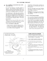
CP-1 CONTROL PACKAGE
Install the cable from the area of the Tem-
perature Sensor (Probe) to the steam
generator’s location. The Temperature Sen-
sor (Probe) MUST be located inside the
steamroom. In steamrooms with singletier
seating the Sensor should be located 6 feet
above the floor, with two tier seating it should
be 7 feet above the floor and in either case
away from the steamhead and steamroom
door. The connector end of the wire must be
installed inside the steamroom.
NOTE
: A
5/8 inch hole should be provided so that the
connector can be passed through the wall for
installation found later in these instructions.
2)
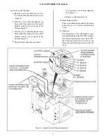
CP-1 System Control Package Installation
Temperature Sensor (Probe ) (for installation
inside the steamroom)
C. 1)
Locate the 2 wire cable described in the
Rough-in section.
a.
Keeping the 5/8 inch hole centered, drill two
1/4 inch holes 2 inches apart. Insert 2-No. 8
plastic anchors into drilled holes.
b.
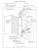
c. Follow Figure 3.
Temperature Control Panel (for installation out-
side the steamroom )
2)
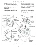
Attach the 3 wires (P1, P2, and P3) from the
Temperature Control Potentiometer to the 3
wire cable in the two-gang box. Note the
colors of wire P1, P2, and P3 are attached to
match the colors of the 3 wire cable to the
potentiometer wire colors.
a.
Secure Temperature Face Plate to the two-
gang box using four (4) machine screws. (See
Figure 4.)
Important:
Care must be taken
to mount Temperature Face Plate properly.
b.
5
Содержание HC-10
Страница 1: ...HEAVY COMMERCIAL STEAMBATH GENERATOR OWNERS MANUAL Models HC 9 Thru HC 18 3 98 Pub No 400 G ...
Страница 12: ......
Страница 13: ......
Страница 14: ......


