ENGLISH
14
14
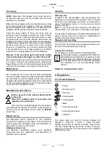
Do not cut bigger materials than the allowed by the
maximum capacity of the tool.
After turning on the tool “ Switch (On)”
softly push the
tool onwards until reaching the workpiece, then slowly
increase the required pressure to produce the least
possible amount of debris.
Never use this tool without stop for over 31 minutes.
Warning!
After completing the cut, lift the tool’s head,
switch it off and wait until the disc has completely stopped
before leaving the tool.
Never work in hazardous areas whith flammable
solids, liquids or gases.
Debris and hot fragments may
cause an explosion.
This tool was specifically designed for ferrous metals
and aluminum only.
Do not try to cut wood, masonry or
any flammable material.
Do not use lubricants or liquids on the tool.
Some metal coatings may be toxic
. Be extra careful
when working with this kind of materials, ask your provider
for further instructions.
This tool was designed for certain tasks only
. Do not
use this tool for other purpposes or tasks than those that it
was designed for. In doubt always ask your provider about
the applications and uses of this tool before working with
it.
Metal dust and debris are sharp and hot and may cause
injuries.
Never touch them bare handed, use a magnet or
another tool to remove them.
This tool is for wet-dry cutting. Designed for ferrous and
non ferrous materials.
This saw uses l 400rpm or more discs. Wood and steel
cutting is not advised as it will drastically reduce the disc
and tool’s lifespan.
Unboxing
Carefully extract the tool and all its accessories. Keep all
the components around until you are sure they all properly
work with the tool.
Do not use the tool until you have fully read and understood
the contents of this user manual.
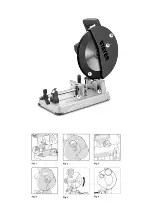
Illustrated components descriptions
1. Lower guard
2. Adjustable front clamp
3. Detachable rear clamp
4. Upper guard
5. Spindle guard
6. Debris deposit
7. Split nut
Disc placement and removal
RELEASE the CUTTING HEAD
The cutting head will automatically lift up once the lower
lock is released.
Releasing the head from the lower lock:
- Carefully press down the cutting head.
- Remove the lock from the head and fix it on its external
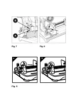
position (Fig. 1) Allow the head to lift up.
If you encounter any difficulties:
- Carefully move the head up and down.
- Completely remove the hook lock and spin it 1/4 to fix it
on its external position.
Note: When the tool is not in use, we recommend locking
it on it’s lower position.
Disc removal
WARNING: Plug off the tool from the power source
before following this steps.
Use a disc that fits the tool requirements. Make sure
its maximum speed suits the tool.
WARNING:
Avoid touching the disc teeth as they may cause
injuries, use gloves.
Make sure the cutting head is lifted up.
- Release the screw that holds the spindle protection and lift
it up to expose the axis (Fig. 2)
- Secure the tool pressing the axis lock button. (Fig. 3)
Use the provided hex key to loosen the screw. (Fig. 4)
Note: The screw is inverted, spin it clockwise to tighteng it
and counter clockwise to loosen it.
- Remove the axis screw, the washer and the guard to use
it later.
- Change the lower protection to the upper protection
spinning it with your hand. (Fig. 5)
- Remove the disc, leaving its inner edge on working
position.
Disc placement
Use a sutiable disc according to the “recoil” section.
Warning
: Avoid touching the disc teeth as they may cause
injuries, use gloves.
- make sure every component is clean and free of debris.
- Install the disc inserting the inner edge on the axis, making
sure the arrow printed on the disc matches the same direction
on the tool carter. (Fig. 6)
- Reinstall the carter, washer and inverted screw.
- Place the spindle guard pressing the safety button.
- Tighten the axis screw using the hex key provided.
- Put back the spindle protection and fix it tightening its screw.
- Make sure you released the spindle lock moving the guard
manually.
- Make sure to remove the hex key and store it in a safe place
for future uses.
- Check that everything is working as intended, specially the
lower guard by moving up and down the cutting head.
Содержание TD355B
Страница 2: ...4 5 1 6 2 3 7...
Страница 3: ...A B Fig 9...


