ENGLISH
15
15
WARNING: After installing a new disc switch on the tool
and let it run without load for several minutes.
Stay away from the disc. If the disc has an undetected issue
it can be noticed with this procedure.
Using the cutting guide and clamp
Warning:
Always use the clamp with no exceptions. If the
workpiece can’t be secured with the clamp do not use it.
Cutting withous safety may cause recoil and accidents.
Always secure the piece in the most stable ans safe
manner. Make sure the workpiece is firmly fixed to the
saw. the 45º cutting guide spins freely to reach the cutting
angle.
Adjust the cutting angle
Note
: the rear clamp can be spinned up to 45º
The rear clamp can be adjusted to 0º (90º towards the
disc) So the disc can cut the material directly placed on
the clamp.
For angle cuts, the rear clamp can be adjusted up to 45º,
With an angle meter for maximum precission.
To adjust the rear clamp angle:
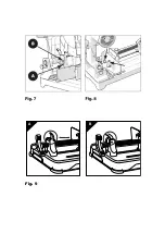
• Loosen the screw M10 and the lever screw. (Fig. 8)
• Spin the clamp to the desired angle.
• Tighten both screws again with the provided hex key.
Note: The lever screw has a coil that alows to reposition
the clamp. Repositioning the lever might be needed to
completely tighten when the rear angle clamp is being
adjusted. To reposition the handle on the screw, pull the
lever upwards and spin it to the desired position (allowing
to tighten the screw) release the lever and tighten the
screw. The fron clamp will automatically compensate any
angle from the rear clamp or the irregulartities from the
workpiece.
Using the clamp
The screw has a simple release system.
- Place the workpiece against the guide in the most safe
manner as possible.
- Lift the split nut. (Fig. 9a)
- Slide the fron clamp to the desired position.
- Place back the split nut. (Fig 9 b)
Warning:
You must place back the split nut in its original
position and properly adjust it to the clamp. Pulling a little
bit the clamp handle just before the sclamp touches the
workpiece will improve the split nut fixing. Using the tool
without the split nut installed is dangerous and should be
avoided.
- Tighten the clamp to secure the workpiece.
- Check the workpiece is properly fixed before working.
Cutting head course
The cutting depth is set from factory and may not need
further adjustments. If the tool is disassembled or for any
other reason the cutting depth needs to be adjusted to
avoid the disc touching the base.
Lower the head and check if the disc has any contact with
the base.
- Release the nut on the cutting limit. (Fig. 7a)
- Spin the screw outwards (Fig. 7b) (counterclockwise) to
reduce the cutting depth.
- Spin the screw inwards (clockwise) to increase the
cutting depth.
- Tighten the nut back when you achieve the desired
cutting depth.
Switch ON /OFF
Make sure the power source matches the tool requirements
and that the trigger is “SWITCHED OFF” before plugging
it to the power source.
This tool includes a safety trigger to switch it on:
- Press the safety lock button with a finger while holding
the handle.
- Press the main trigger at the same time to switch on the
tool.
WARNING: Never switch on the tool while the disc is
in contact with any surface or material
Debris removal
This tool has a metal debris deposit.
Once the deposit is full the debris must be removed. To do
this unplug the tool from the power source..
To check the debris deposit:
- Spin the lock lever horizontally to access the deposit.
- Empty the deposit in a suitable recycling point.
- It is advisable to use a breathing mask to empty the
deposit.
- Place back the deposit and spin the lever vertically to fix
it to the tool.
Freshly cut debris might be sharp and very hot. Be careful
when removing them, avoid touching them with your
hands or body. Do not dispose of debris on any bin or
container as they may cause a fire.
Safety transport chain use
To increase the safety whil transporting the tool the safety
chain must be used.Simply lower the head and place the
chain so the head stays down.
Lower saw guards
This guardar are really important for your safety.
Each time you use the saw make sure they can rotate
freely and that they quickly return to their original position.
Before using the tool clean any dust and debry that migh
be around the carter. DO NOT LUBRICATE THIS ZONE,
FIRE WARNING.
The carter has a lubrified dry coating
. NEVER block
the carter on an open position. NEVER use the saw if you
are not working.
If the saw is slow take it to the closest customer service
available.
Содержание TD355B
Страница 2: ...4 5 1 6 2 3 7...
Страница 3: ...A B Fig 9...


