17 of 30
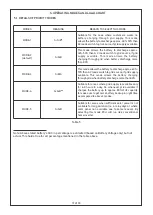
BATT LOW : This red LED glow when your battery is low/discharged. Once Battery voltage falls below
Battery Under Voltage set value; Inverter will shut down and disconnect the load to stop further
discharging of battery. Next, “BATT. LOW” indication will appear on the display. Now Inverter will
again given the O/P to load only when Battery Voltage rises up to more than float voltage set value.
FAULT : This red LED glow if any Fault occurs.
INV ON/OFF : Press and hold button to turn on your PCU, green LED nearby button will start glowing,
which indicates inverter is switched ON.
PRESS AND HOLD BUTTON TO TURN ON YOUR PCU, GREEN LED NEARBY BUTTON WILL START
GLOWING, WHICH INDICATES INVERTER IS SWITCHED ON.
LED OF CHARGING SOURCE WILL KEEP BLINKING DURING CHARGING.
4.5 MENU SETTING FLOW CHART
Figure 14
Disclaimer:- Due to technical innovations LCD display design or look of the PCU system can be changed by manufacturer.
IN USER SETTING MODE BATTERY TYPE, BATTERY CAPACITY & PRIORITY MODE MUST BE CHOSEN
PROPERLY AS PER YOUR REQUIREMENT.
DATA MODE
DAY KWH
SET
SET
SETTING
MODE
INC / DEC
LONG PRESS SET
P
DATE
SET
A
F
A
P
L P
MONTHLY KWH
INC
U
P
DEC
YEARLY KWH
INC
U
DEC
SET
-
P
A
F
A
ENTER
ENTER
ENTER
EXIT
13: 0
6
:45
0
6
: 17
2017
SET
SET
00 03.54
DATE
TIME
YEAR
00 03.54
00 03.54
ENTER
EXIT
EXIT
EXIT
PC -Ue
L
U
14 4
INC/DEC
SET
SET
INC
INC
VRLA BATT
LM BATT
NI-CAD
PRIORITY MODE
P
P-UE
U LA
U
DATE
TIME
YEAR
48 - 1
1-C A
P
P
E
5-6-
P
INC/DEC
ENTER
ENTER
EXIT
EXIT
SET
SET
U5
FC
F
5 E
F
DATE
5E
F
C AL 1
P
Содержание SEOG Series
Страница 1: ...Optional two way IoT access STATCON Inspire Innovate Implement ENERGIAA...
Страница 12: ...This image shows a typical single line diagram showing use of SPD and earth connection there of 11 of 30...
Страница 27: ...26 of 30 APPENDIX 2 TECHNICAL SPECIFICATIONS...
Страница 28: ...27 of 30...

