


16 of 30
4.3 MENU SETTING
Long Press key SET to enter MENU setting Mode.
In MENU press key INC successively to go in DATA LOGGING MODE, USER MODE, USER SETTING
MODE, FACTORY SETTING MODE and PARAMETER CALIBRATION MODE. To exit from this mode press
ENTER.
4.3.1 DATA LOGGING MODE
Press key SET to enter in data mode when displayed on scree.
Press key SET to see days unit generation (KWh) day wise data.
Press key SET to see monthly unit generation (Kwh) data.
Press key SET to see year wise (Kwh) data.
Press key ENTER to exit this mode.
4.3.3 FACTORY SETTINGS MODE
This mode is password protected. (to be operated only by trained personnel of company).
4.3.4 PARAMETER CALIBRATION MODE
This mode is password protected. (to be operated only by trained personnel of company).
4.3.2 USER SETTING MODE
Press key SET to enter in user mode when displayed on screen.
After entering in user mode it will show software versions.
PC-UEr (XX.X) and dp-UEr (X.X)
After this, it will show rating of your PCU. e.g. 48-4 kVA.
Press key INC to select your battery type (LM/VRLA/NI-CAD). Now press key SET to select battery
capacity (Ah).
Using INC/DEC keys, we can change battery capacity. Now press SET key to choose priority mode
now.
Press key INC/DEC to choose your source priority mode (S>G>B*/S>G>B/G>B>G/S>G>B**/G>S>B).
Press key ENTER to save your settings. It will automatically return to main menu.
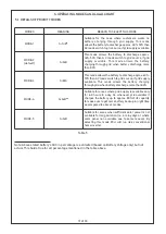
4.4 LED INDICATION
POWER
GRID
SOLAR
INVERTER
BATT. LOW
FAULT
POWER : This green LED indicates PCU’s control circuitry is power ON.
INVERTER ON : This yellow LED glows when AC load is on INVERTER.
SOLAR ON : This yellow LED glows in steady state - this tells that the solar present and the
charging is completed/stoped. When blinking, it tells the solar is present and the charging is in
process
GRID ON : This yellow LED glows in steady state - this tells that grid is present and the load are
bypassed on GRID supply. When blinking with 1 second interval, it tells that (i)the grid is present, (ii)
the grid charging is in process and , (iii) the load is running on GRID supply. When blinking with a 5
second interval, it means that the GRID supply is available and the loads are running on PV+Battery.
Figure 13
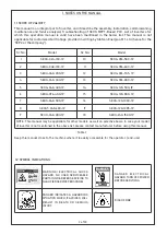
Содержание SEOG Series
Страница 1: ...Optional two way IoT access STATCON Inspire Innovate Implement ENERGIAA...
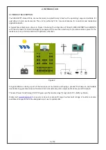
Страница 12: ...This image shows a typical single line diagram showing use of SPD and earth connection there of 11 of 30...
Страница 27: ...26 of 30 APPENDIX 2 TECHNICAL SPECIFICATIONS...
Страница 28: ...27 of 30...


