
12
13
PART 2
Under Load (accessories ON):
Next, load the alternator by turning on as many accessories as possible (except for A/C and
Defrost).
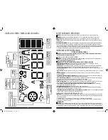
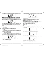
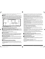
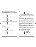
1. Press the Alternator Check Button to start the check. The backlit LCD screen will display the following to indicate the unit is
analyzing the alternator:
The Battery Status Icon will light solid and the Alternator Icon will flash.
2. If the unit detects that the alternator is good, the backlit LCD screen will display the following:
The Battery Status Icon, Alternator Icon, and “ALT GOOD” will light solid.
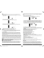
3. If the unit detects that the alternator is out of typical voltage range, the backlit LCD screen will display the following:
The Battery Status Icon, Alternator Icon and "ALT" will light solid. The Fault Icon will flash.
4. Press the Alternator Check Button again to stop the test and turn off the unit.
IMPORTANT:
Always turn the unit off when not in use. Recharge this unit fully after each use.
Notes:
The unit may detect that the alternator is out of typical voltage range because someone has added a number of accessory loads on the charging
system, thereby increasing current demand from the alternator. MAKE SURE THAT THE ALTERNATOR IS RATED TO SUPPORT THE APPLICATION.
This check may not be accurate for every make, manufacturer and model of vehicle. Check only 12 volt systems.
PORTABLE COMPRESSOR
The built-in 12 volt DC compressor is the ultimate compressor for all vehicle tires, trailer tires and recreational inflatables.
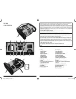
A nozzle adaptor is supplied that screws onto the end of the SureFit™ nozzle at the free end of the compressor hose. The
compressor hose with tire fitting is stored in the compressor hose storage compartment. Refer to the “Features” illustration
for locations of compressor hose. The Compressor Power Button and Compressor Pressure Control Buttons are located on the
control panel on the front of the unit.
Before proceeding, check the unit’s battery status on the LCD screen. Four solid bars in the battery icon indicates a full battery.
When the battery level is nearly empty with only one solid bar, the unit MUST be recharged before use or the unit’s built-in low
voltage protection will activate. The empty Battery Status Icon will flash for a short period of time before automatic shut down.
The compressor may be used by removing the air hose from the storage hatch and if required, fitting the nozzle adapter to the
air hose. The compressor is capable of inflating up to 120 pounds per square inch (psi) pressure. The compressor can operate
long enough to fill up to 3 average sized tires before the battery must be recharged. Return hose to the storage compartment
after use.
IMPORTANT:
Make sure the Jump Starter Power Button has been turned off before attempting to use the unit as a Compressor.
WARNING – TO REDUCE THE RISK OF INJURY OR PROPERTY DAMAGE: Follow all safety instructions found in the “Specific
Safety Instructions For Compressors” section of this instruction manual.
CAUTION – TO REDUCE THE RISK OF PROPERTY DAMAGE:
When the compressor is operated at a low PSI, the unit may start in low and gradually rev up. When the compressor is
operated at higher PSIs, the unit may operate normally for several minutes, then rev down for a few minutes before returning
to normal operation. This feature protects the unit from overheating during normal use. In any event, do not operate
compressor continuously for extended periods of time (approximately 10 minutes, depending on ambient temperatures), as
it may overheat. This could damage the compressor. If the compressor must be operated for longer periods: every 10 minutes
press the Compressor Power Button to turn the compressor off, then restart after a cooling down period of approximately 30
minutes.
Inflating Tires or Products With Valve Stems
1. Screw the SureFit™ nozzle onto the valve stem. Do not overtighten.
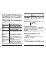
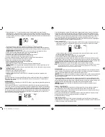
2. Press the Compressor Power Button. A beep will sound and the backlit LCD screen will display the following:
The Compressor Icon will light and the digital display will alternately show the flashing pre-set psi value (that was last set by
the compressor pressure control buttons) and the current pressure of the item being inflated (which will light solid).
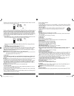
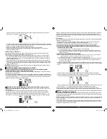
3. Press the “+” and “–” Pressure Control Buttons to set the desired pressure from a range pre-set values (between 3 and 120),
which will display on the backlit LCD screen. The unit will sound a beep with each press of the buttons (holding the button
speeds up the upward or downward value selection). Once the desired pressure has been entered, release the button and
the flashing digital display will show the new selected pressure, as follows:
The new selected value is now stored in the unit’s memory until it is manually reset.
4. Press the Compressor Power Button once more to begin inflating. The Compressor Icon will flash and the digital display will
only show the current pressure value (which will light solid) to indicate the compressor is activated. Monitor the pressure on
the LCD screen.
IMPORTANT NOTE:
To interrupt during inflation, press the Compressor Power Button again.
5. When desired pre-set pressure is reached, the compressor will automatically stop.
6. Press the Compressor Power Button again to turn off the unit.
7. Unscrew and remove the SureFit™ nozzle from the valve stem.
8. Allow the unit to cool, then recharge before storing away.
9. Store the compressor hose and SureFit™ nozzle in storage compartment.
Inflating Other Inflatables Without Valve Stems
Inflation of other items requires use of the nozzle adapter.
1. Screw the nozzle adapter into the SureFit™ nozzle. Do not overtighten.
2. Insert the nozzle adapter into item to be inflated.
3. Follow steps 2 through 4 of the “Inflating Tires or Products With Valve Stems” section.
IMPORTANT:
Small items such as volleyballs, footballs, etc. inflate very rapidly. Keep this in mind when setting pressure. Take
extra care not to over-inflate.
4. When the desired pressure is reached, the compressor will automatically stop. Press the Compressor Power Button again to
turn off the unit.
5. Disconnect the adapter from the inflated item.
6. Unscrew and remove the nozzle adapter from the SureFit™ nozzle.
7. Allow the unit to cool, then recharge before storing away.
8. Store the compressor hose, SureFit™ nozzle and nozzle adapter in the storage compartment.
USB PORTS
The USB Power Button and the four USB Ports are located on the left hand side of unit. The USB Power/Fault Indicator is a
translucent ring around each of the four USB Ports. Refer to the "Features" section to locate.
IMPORTANT NOTES:
The top two USB Ports provide a total of 3.1A (5V each). The bottom two USB Ports provide a total of 3.1A (5V each).
When the USB Ports are in use, the unit will monitor for the following USB fault conditions on all the USB Ports: thermal fault,
low battery voltage fault, overload and short circuit. The USB Power/Fault Indicators are divided into an upper set and a lower
set. The upper set detects fault conditions in the first two USB Ports; the lower set monitors in the last two USB Ports. If a
fault condition exists in either of the first two USB Ports, the upper set of USB Power/Fault Indicators will flash blue. If a fault
PP1DCS_ManualENSP_072116.indd 12-13
7/27/2016 10:20:07 AM