1 – 4
Overview
output power optically. The CP setpoint can be given either in raw
microamps of photodiode current, or in optical power as milliwatts
(given a photodiode responsivity value).
For both ranges and operating modes of the LD driver, a DC-coupled
analog modulation input is available on the front panel. Modulation
can be used on all ranges and operating modes, and can be configured
for low or high bandwidth. When unused, the modulation input
relay should be opened by setting “Modulate enable” to “N” in the
Laser Configure menu. Commanding the modulation input o
ff
in
this way, when not in use, will result in slightly lower current noise.
1.2.1.2 TEC controller
The TEC controller section of the LDC500 delivers high performance
temperature control for thermally stabilizing the laser diode. Most
commonly-used thermal sensors are supported, including thermis-
tors, RTDs, LM335-class voltage-output IC sensors, and AD590-class
current-output IC sensors. A 36 W,
±
4
.
5 A bipolar current source
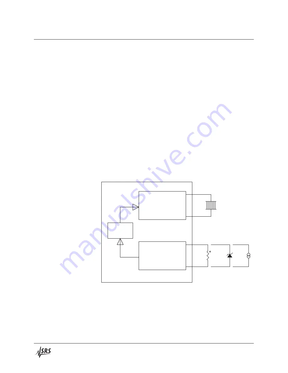
drives the thermoelectric cooler (TEC) module of the laser. A block
diagram of the TEC circuitry is in Figure 1.3.
TEC
Controller
sensor
readout
TEC
Current
Source
+
–
MCU
TEC
t
LM335
AD590
Figure 1.3: The TEC controller (simplified).
Two operating modes are available for the TEC controller. In constant
temperature (CT) mode, a digital proportional-integral-di
ff
erential
(
PID
) control algorithm adjusts the TEC output current to maintain
the temperature sensor at a desired temperature. For characteriz-
ing TEC modules, a second operating mode–constant current (CC)–
LDC500 Series Laser Diode Controllers
Содержание LDC500
Страница 14: ...xii General Information LDC500 Series Laser Diode Controllers...
Страница 50: ...2 22 Getting Started LDC500 Series Laser Diode Controllers...
Страница 128: ...4 64 Remote Operation LDC500 Series Laser Diode Controllers...
Страница 136: ...5 8 Error Messages LDC500 Series Laser Diode Controllers...


