background image


Error Timeout 


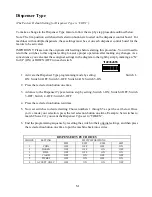
(The Factory Default Setting for Error Timeout is “15 MINUTES”). 


To make a change to the Error Timeout feature, follow the step by step procedure outlined below.  


Note: The five-position switch and red selection button are located on the dispenser control board of 
the device marked “Primary”. For machines with multiple bill acceptors, these settings must be set on 
the dispenser control board that each bill acceptor is plugged in to. 


IMPORTANT: Please note the original switch settings before starting this procedure. You will need to 
return the switches to this original setting to assure proper operation after making any changes. As a 
convenience, you can enter these original settings in the diagram to the right by simply 
marking an “X” for UP or DOWN on each switch.  


1.


Activate  the  Error  Timeout  programming  mode  by  setting:  Switch  1–ON; 
Switch 2-OFF; Switch 3-OFF; Switch 4-ON; Switch 5-ON 


2.


Press the red selection button one time. 


3.


Advance to the Error Timeout selection step by setting; Switch 1-ON; Switch 2-OFF; Switch 
3-OFF; Switch 4 –OFF; Switch 5-OFF 


4.


Press the red selection button one time. 


5.


Now  set  switches  to  desired  setting  Choice  numbers  1  through  15  as  per  the  cart  below. 
Example:    Set  switches  to  match  Choice  5  if  you  want  the  Error  Timeout  feature  set  to  20 
minutes.  Once you’ve made your selection, press the red selection button one time. 


6.


End the programming sequence by resetting the switch to their original settings, and then press 
the red selection button one time to put the machine back into service. 


Note: Error Timeout will only reset the machine from a Fast Vend or “Stringing” error.  Choosing 0 
minutes will deactivate this automatic reset feature.


ERROR TIMEOUT CHOICES


CHOICE 

SETTING 

(minutes) 

SWITCH POSITIONS 

SW2 

SW3 

SW4 

SW5 

DOWN 

DOWN 

DOWN 

UP 

DOWN 

DOWN 

UP 

DOWN 

10 

DOWN 

DOWN 

UP 

UP 

15 

DOWN 

UP 

DOWN 

DOWN 

20 

DOWN 

UP 

DOWN 

UP 

25 

DOWN 

UP 

UP 

DOWN 

30 

DOWN 

UP 

UP 

UP 

35 

UP 

DOWN 

DOWN 

DOWN 

40 

UP 

DOWN 

DOWN 

UP 

10 

45 

UP 

DOWN 

UP 

DOWN 

11 

50 

UP 

DOWN 

UP 

UP 

12 

55 

UP 

UP 

DOWN 

DOWN 

13 

60 

UP 

UP 

DOWN 

UP 

14 

65 

UP 

UP 

UP 

DOWN 

15 

70 

UP 

UP 

UP 

UP 

12 345


Содержание BCX Series

Страница 1: ......

Страница 2: ......

Страница 3: ... IF THE PRODUCT OR ANY COMPONENT OR PART THEREOF IS RETURNED TO MANUFACTURERS FACTORY OR ONE OF ITS COMPANY OWNED SERVICE CENTERS TRANSPORTATION CHARGES SHALL BE PREPAID BY THE OWNER Each Product shipped from the factory contains Owner s Manuals Before shipping a Product to Manufacturer or one of its company owned service centers for warranty work the owner shall be certain that the source of diff...

Страница 4: ... 8 The Locations Electrical Supply 20 3 0 Lock Operation 21 4 0 Understanding Machine Operating Concepts 22 4 1 Dual Redundancy Operating Mode 24 5 0 Machine and Device Features 25 5 1 Bill Acceptance and Bill Security Feature Type Device 25 5 2 Fast Vend Shutoff Feature Type Machine 25 5 3 Error Timeout Feature Type Machine and Device 26 5 4 Serial Control Feature Type Machine 26 5 5 Power Reset ...

Страница 5: ... Coin Dispenser Counter 40 6 6 Coin Dispenser Sold Out Configurations 40 7 0 Bill Dispenser 41 7 1 Fujitsu Bill Dispenser 41 7 1 1 Bill Dispenser Cassette Magnets 41 7 1 2 How To Set Cartridge Position Magnets 41 7 1 3 Setting The Magnets for The Correct Cassette Locations 42 7 1 4 Setting the cassette bill denomination 43 8 0 Part Ordering Information 43 8 1 Bill Acceptors 44 8 2 Interconnecting ...

Страница 6: ...anger The machine should be located in an area where it will not be directly exposed to the elements excessive dust dirt direct sunlight and or direct rainfall We recommend the use of a canopy over the machine to ensure a longer trouble free service life as well as to provide a convenience for your customers The machine power cord should be secured in a manner that will prevent accidental or inten...

Страница 7: ...eads from accumulating in your coin dispenser Clean coffee cans or plastic pails can also be used to fill the coin dispensers Type No of Coins Value Nickel Dispenser 3 800 190 Dime Dispenser 7 800 780 Quarter Dispenser 3 200 800 Dollar Dispenser 2 400 2 400 1 5 Loading the Bill Dispenser Cartridge If your machine is equipped with a bill dispenser read this section carefully Bill dispenser reliabil...

Страница 8: ...s should be removed from the bill tray Do not attempt to reuse them as they will not likely dispense the second time either SOLD OUT GENERAL A small number of bills will remain in the dispenser when it becomes sold out This insures that enough bills remain to finish any dispense that is in progress These bills may be reloaded along with new bills SOLD OUT FUJITSU 40 to 70 bills will remain in the ...

Страница 9: ...7 BILL DISPENSER MODELS AVAILABLE FUJITSU MODEL F50 FUJITSU MODEL F53 Glory MinMech Glory MultiMech ...

Страница 10: ...y do not include the rotate plate STEP 1 Slide pull dispenser out as far as it will go STEP 2 Swivel the dispenser rear loads only to allow additional bill compartment access STEP 3 Open the bill compartment door of the dispenser STEP 4 Slide the pressure plate back and snap into position STEP 5 Load bills so they are standing on end Release the pressure plate so the bills are pushed forward ...

Страница 11: ...r cartridge STEP 1 Push green release button on front of cassette to remove it from the dispenser STEP 2 Press green button on back of cassette to open it STEP 3 Lift pressure plate in rear as shown STEP 4 Lift pressure plate in front and load bills STEP 5 Return pressure plates to original position and install cassette into correct location in the dispenser ...

Страница 12: ...d conditioned bills STEP 1 Use the handle to pull the cassette from the bill dispenser STEP 2 Insert and rotate the key Slide the latch to the right while lifting the lid STEP 1 Use the handle to pull the cassette from the bill dispenser STEP 3 Pull the green pressure plate towards you and insert a stack of good conditioned bills STEP 4 Return the pressure plate to the original position close the ...

Страница 13: ...ing An Error Condition On The Dispenser If an error condition is present on any dispenser the status LED will be flashing at a rate of one flash per second and there will be a brief delay LED will be off for approx 3 seconds between consecutive flashes This flash pattern indicates an error condition If this occurs count the number of flashes between the pause Do this several times to verify the co...

Страница 14: ...ble See the pictures below for the common access door locations Pyramid Acceptor Mars Acceptor Coinco Acceptor Each dispenser is equipped with a push button that can be used to reset the dispenser from an error condition It is only necessary to reset the coin dispenser that is displaying the error flash code Allow at least 45 seconds after releasing the button for the entire reset process to be co...

Страница 15: ...chines Out Of Service lamp to change from the constant ON state to a BLINKING or OFF state Make sure that the dispenser is flashing a dispenser sold out code If any other flash code is shown when pressing the Push Button it will reset the dispenser You will have to power cycle the dispenser again Next press and release the Push Button see diagram above for location The dispenser will begin dispens...

Страница 16: ...pty the box and then return it to the original position The coin box should be free to be removed without the use of tools Some models have a shipping bolt or nut that is used to attach the coin box to the mount during shipping If this has not been removed remove it at this time The shipping bolt or nut is no longer required NOTE ON THE MC700 CHANGER REMOVE THE 2 SCREWS IN THE BOTTOM OF THE CHANGE...

Страница 17: ...his device device draws 100 load when on is equal to the wattage of the heating element A 100 Watt heating element in addition to the momentary power supply draw of 80W would bring the total maximum power consumption of the machine to 180 Watts The maximum wattage for the entire machine including ancillary items should not be allowed to exceed 360 Watts 1 13 Environmental Considerations Advance co...

Страница 18: ...l acceptor supplied with your machine is limited to the particular manufacturers specifications See the Bill Acceptor owners manual for the recommended operating specifications NOTE Most OEM bill acceptors are specified to operate properly between 0o C 32o F and 50o C 122o F ambient temperature These conditions meet our recommended specifications for a moderate environment application If the preca...

Страница 19: ... of the self tapping screw Install header using self tapping screws and flat washers included to top of cabinet All screws should be tightened till snug do not over tighten Make sure the screws will not damage anything inside the machines FOR MORE INFORMATION ON THE INSTALLATION AND ADA COMPLIANCE SEE MANUAL 8M00356 MODULAR SERIES INSTALLATION GUIDE The ADA Compliance Chart of installation rough o...

Страница 20: ...Load Changers A rear load changer cabinet must mount through a hole in the wall The stainless steel front plate which extends 2 inches beyond the cabinet on all sides must be tight against the wall surface The cabinet will be 13 18 deep Its protrusion into the back room will be the difference between this depth and the thickness of your wall Allow for proper door swing Also lay a bead of caulking ...

Страница 21: ...stallation If the coin dispensers have been shipped in separate carton s do not remove or disconnect any components Use four 1 4 inch diameter bolts for mounting CAUTION Even the slightest uneven surface can cause cabinet distortion when mounting bolts are tightened This can cause the doors to fit unevenly when closed This distortion can occur even more easily on large cabinets Should this occur i...

Страница 22: ... or if dedicated line is not feasible the use of a high quality surge suppressor same as used for home computers is recommended IMPORTANT This machine must be grounded through a properly installed 3rd wire ground which extends intact to the main service panel 2 8 The Locations Electrical Supply If this machine has a service cord that ends in a 3 pin connector The wall receptacle you plug the machi...

Страница 23: ...or lock mechanism approximately five turns then pull the door open The lock handle must be parallel to the floor for the lock to disengage on MC100 MC200 MC400RL MC700 and MC900 cabinets the lock must be perpendicular to the floor on the MC300RL and MC500RL DA cabinet To lock the door turn the handle parallel to the floor then push the door closed The lock will be automatically engaged as the door...

Страница 24: ... of the table the value is identified as Programmed This indicates that the dispenser value is stored in memory as opposed to being shown on the DIP switch This setting is only used if the item being dispensed is not the equivalent of a standard coin value Read the following sections for more information about the DIP switches The most common Value of coin dispenser is a quarter This would be foun...

Страница 25: ...rced Vend Feature DEVICE MACHINE FEATURE DIFFERENCES DEVICE FEATURES Each device dispenser is capable of managing its own features and related functions These features will be referred to as DEVICE FEATURES MACHINE FEATURES In addition to managing its own Device Features each device dispenser can also manage machine features Machine Features and related functions are those that have to do with the...

Страница 26: ...nto the coin cup on the side of the machine that the bill was deposited into Electrical Connection For Dual Redundancy Mode Operation With the machine power off connect a control cable 4C00316 short cable or 4C00299 long cable between two coin dispensers The cable ends are color coded to correspond with the color code dot on the dispenser logic board If the machine was shipped to you in the Indepe...

Страница 27: ...l acceptance can be set to yes or no for each denomination As an example if you decide not to accept twenty dollar bills you would select Security High and Accept No 5 2 Fast Vend Shutoff Feature Type Machine Factory Default Settings Time Period 15 minutes for all bill denominations Max Qty of each bill supported based on country is U S currency 1 45 2 45 5 20 10 10 20 5 50 2 100 2 Canadian curren...

Страница 28: ...e dispenser None A computer will not be communicating to the dispenser This is the default dispenser mode Control A computer will control the dispensers using the Standard Change Maker protocol Communication every 20 seconds is required from the computer or the machine will go offline This is done so bills and coins will not be stolen because the computer is not available Control Relaxed A compute...

Страница 29: ...ser fails All remaining vends will be issued from the other quarter coin dispenser until the failed hopper is returned to the operating condition If at any time the nickel coin dispenser should fail the machine will go out of service 5 8 Forced Dispense Feature Feature Type Machine Default Settings 0 This feature allows you to force a dispense amount quantity from the Primary Device The Make Best ...

Страница 30: ...Feature would normally force 20 nickels to be dispensed 5 accepted Payout is 20 from the Primary Device and 4 from the Secondary Device 5 10 Accumulate Feature Type Machine Default Settings Disabled When this feature is enabled a dispense will not occur until enough money has been accepted to meet or exceed the value of the PRIMARY DEVICE Make Best Change will then occur 5 11 Dispenser Type Featur...

Страница 31: ... feature False errors may occur if bills are rapidly fed into the machine 5 14 Count Out Items Feature Type Device Default Settings Dollars This feature is only necessary if you wish to count the number of items dispensed rather than the dollar amount dispensed 5 15 No Bill Acceptor Shutdown Feature Type Machine Default Settings NO Available in software version 01 037 or newer This setting can be ...

Страница 32: ... or newer This feature is used to automatically clear an overpay error Be careful using this in that it can hide a serious problem This uses the Error Timeout of the primary dispenser or EF if you have one 5 20 Bonus Tokens Feature Type Machine Default Settings 0 Bonus tokens cards tickets are those that are issued at no cost In other words they are given away as a bonus to the machine user These ...

Страница 33: ...value of each cassette will need to be setup Note Any cassette that does not have a value programmed will not be used for the dispense cycle and will not appear in the Configuration Report on an Extended Function module Steps 1 4 are used for the top cassette steps 5 8 are used for the next one down steps 9 12 are used for cassette the next one down steps 13 16 are used for the next one down etc E...

Страница 34: ...ault are used in applications where two side by side tickets are dispensed while the ticket issuing device only counts notch one ticket This unique circumstance typically occurs when two 1 ticket rolls or fan fold are manufactured side by side and dispensed from ticket issuing device capable of dispensing 2 wide tickets 5 25 Bin Low Count Value Feature Type Device Default Settings 30 Available in ...

Страница 35: ...ith the same denomination of bill Setting the override to on for a cassette will disable the sold out detector and allow the 40 70 bills that typically remain to be dispensed This feature will allow one cassette to dispense every bill before the next cassette with the same bill denomination is activated Steps 4 Enter override for cassette 1 Steps 5 Enter override for cassette 2 Steps 6 Enter overr...

Страница 36: ...te the particular error If a two digit flash code is present a short pause will occur between the first digit and the second digit of the flash code Following are examples EXAMPLE OF A FLASH CODE ERROR 9 EXAMPLE OF A FLASH CODE ERROR 34 FLASH 3 TIMES SHORT PAUSE FLASH 4 TIMES LONG PAUSE FLASH 9 TIMES LONG PAUSE Yellow LED Status Green LED Power Red LED Coin ...

Страница 37: ... bill acceptor and refer to the bill acceptor owners manual for additional troubleshooting assistance Ensure the bill acceptor cable is plugged in properly Check the data cable gray phone style cable labeled 4C00299 to ensure it is plugged in properly The cable is color coded at each end Be sure the blue cable end is connected to the blue connector on the circuit board 3 THE BILL STACKER IS MISSIN...

Страница 38: ...nd associated count were cleared This error is typically caused by excessive power surges Install a surge filter on the power line to the machine 14 OVERPAY LOGIC ERR The device calculated it was told to dispense to many items Check Dispense limit settings for the affected device Check the Program settings 15 30 TRACKING CODES These codes are intended for use by SCM troubleshooting personnel If co...

Страница 39: ...ce light is on solid and the machine won t take a bill Refer to the troubleshooting section of this manual for help on isolating the problem source My acceptor takes the money but the hopper won t dispense change Check the dispenser labeled PRIMARY DEVICE for a flash code and use it to isolate the source Also check all connections Dump the hopper and press the hopper dump button and verify that th...

Страница 40: ...m bill path Use clean damp rag to wipe off optic sensors on the upper and lower track assemblies Review OEM manufacturer s information for additional tips Coin Token Hopper Dump hopper once every six months and remove bent coins or tokens Use canned air to remove dust and debris from hopper shell and dispenser area Use a clean Q tip and wipe off the coin interrupters located on either side of the ...

Страница 41: ...lease the card 2 Press the red reset button 3 The red LED should come on solid and the yellow LED will flash quickly when the memory is being erased 4 The red LED blinks quickly while the yellow LED is off when the memory is being programmed 5 When the yellow light stops flashing quickly you can remove the card Coin Interrupter Optics Micro SD Card Connector ...

Страница 42: ...leave enough coins in the dispenser to ensure that the last person to use the machine before it shuts off due to an empty condition receives all of their change Therefore the sold out level setting should match or exceed the value of the largest bill denomination to be accepted typically a 20 bill To determine how to set the optimum sold out level see the pictures below To access the sold out leve...

Страница 43: ... it become necessary at any time Example if a replacement cassette is required or if an additional dispense cartridge is added to upgrade from a dual cassette dispenser to make it a triple cassette dispenser 7 1 2 How To Set Cartridge Position Magnets Use the procedure below to set the cartridge position magnets These magnets are used to make sure the cassettes are not inadvertently placed into th...

Страница 44: ...t that is used to identify and verify that the correct cassette is installed in the correct location The top cassette should always be set to A the second to B the third to C and the fourth to D if needed A B C D Slot locations for magnets See label inside A B C Fourth Cassette Will Be Placed Here If Needed A B C D ...

Страница 45: ...ays remove power from your machine prior to removal of a component 5 Remove the faulty component from the changer cabinet 6 If the component is to be returned to the factory or service center pack the component in the original factory packaging if possible If the original packaging is not available use a suitable substitute Care should be taken to prevent damage to the components from electrostati...

Страница 46: ...ex 100P Standard Bezel 500 bill stacker 5V00333 Pyramid 5400 Mex 500P Standard Bezel 500 bill stacker 5V00344 Pyramid 5402 Aus 100 External Bezel 500 bill stacker 5V00351 Cashcode Currenza Can 20 400 bill stacker 5V00352 CoinCo Vantage USA 20 500 bill stacker 5V00353 CoinCo Vantage Can 20 500 bill stacker 8 2 Interconnecting Cables Part Number Description 4C00263 MDB Bill Acceptor 4C00299 Cable Co...

Страница 47: ...3 2K Quarter Rear Load 5H00353 Hopper 3 2K Dollar Rear Load Call for other options 8 6 Coin Dispenser Part Numbers Part Number Description 2P00101 Quarter adapter ring 4M01358 Quarter feed mechanism 4M01374 Quarter dispense mechanism 4M00675 Coin Dispenser Housing 2P00105 Dollar adapter ring 4M00581 Dollar feed mechanism 4M00688 Dollar dispense mechanism 4A00121 Coin Dispenser Funnel Assembly 4C00...

Страница 48: ...S Ø1 125 25 00 6 19 4 60 1 61 1 64 Ø1 125 Ø0 313 MOUNTING HOLES 4 PLACES 1 75 11 75 1 44 3 50 11 00 1 55 5 10 1 33 7 67 Ø0 313 MOUNTING HOLES 4 PLACES Ø1 125 DIMENSIONS Width Height Depth Weight Cabinet 8 50 32 00 13 00 70 lbs Base 8 50 30 00 13 00 40 lbs Header 8 50 10 00 13 00 10 lbs BILL ACCEPTOR COIN DISPENSER MOUNTING HOLE LOCATIONS BOTTOM SIDE BACK SIDE COMPONENT LOCATIONS BASE HEADER ASSEMB...

Страница 49: ... HEADER ASSEMBLY DIMENSIONS Width Height Depth Weight Cabinet 13 50 26 00 13 00 106 lbs Base 13 50 30 00 13 00 51 lbs Header 13 50 16 00 13 00 15 lbs COMPONENT LOCATIONS MOUNTING HOLE LOCATIONS BACK SIDE BOTTOM SIDE ...

Страница 50: ... Width Height Depth Weight Cabinet 13 50 28 00 13 00 131 lbs Faceplate 17 50 32 00 COMPONENT LOCATIONS DIMENSIONS Width Height Depth Weight Cabinet 9 00 32 00 13 00 90 lbs Faceplate 13 00 36 00 COMPONENT LOCATIONS LEFT SIDE LEFT SIDE ...

Страница 51: ... RL MC520 RL MC525RL CC MC535RL CC MC550 RL BILL ACCEPTOR COIN ACCEPTOR COIN DISPENSER COMPONENT LOCATIONS DIMENSIONS Width Height Depth Weight Cabinet 18 00 32 00 13 00 175 lbs Faceplate 22 50 36 00 LEFT SIDE ...

Страница 52: ...50 MC600 RL DIMENSIONS Width Height Depth Weight Cabinet 29 00 34 00 18 00 307 lbs Faceplate 33 00 38 00 BILL ACCEPTORS COIN DISPENSER S COMPONENT LOCATIONS COIN ACCEPTOR LEFT ...

Страница 53: ...Cabinet 16 75 27 875 13 00 158 lbs Base 16 75 30 625 13 00 55 lbs Header 16 75 13 625 13 00 15 lbs Pedestal 22 00 24 625 17 00 75 lbs BASE AND HEADER ASSEMBLY COINS DISPENSERS COIN ACCEPTOR BILL ACCEPTOR COMPONENT LOCATIONS MOUNTING HOLE LOCATIONS ...

Страница 54: ...52 MC800 RIGHT BOTTOM DIMENSIONS Width Height Depth Weight Cabinet 26 00 34 00 18 00 250 lbs Base 26 00 26 00 18 00 110 lbs BILL ACCEPTORS COIN DISPENSERS COMPONENT LOCATIONS BASE ...

Страница 55: ...LOCATIONS BACK SIDE BOTTOM SIDE DIMENSIONS Width Height Depth Weight Cabinet 28 00 56 00 18 00 425 lbs MC900 5 00 37 39 3 32 19 00 19 86 4 07 16 75 Ø1 125 POWER OUT 2 PLACES Ø0 515 MOUNTING HOLES 6 PLACES Ø0 875 MOUNTING HOLES 4 PLACES 22 00 12 50 3 36 2 88 ...

Страница 56: ...NS Width Height Depth Weight Cabinet 19 00 28 00 18 00 150 lbs Pedestal 19 00 30 00 18 00 75 lbs COMPONENT LOCATIONS BILL ACCEPTOR BILL DISPENSER RIGHT SIDE BOTTOM SIDE BILL ACCEPTOR BILL DISPENSER 3 4 DISPENSERS 1 2 DISPENSERS ...

Страница 57: ...BX1010 RL FUJITSU DIMENSIONS Width Height Depth Weight Cabinet 16 75 28 00 18 00 130 lbs Faceplate 21 00 32 00 BILL ACCEPTOR FUJITSU BILL DISPENSER RIGHT SIDE COMPONENT LOCATIONS EF MODULE COUNTERS PRINTER ...

Страница 58: ...56 BX1010 FL FUJITSU DIMENSIONS Width Height Depth Weight Cabinet 18 00 38 00 18 00 175 lbs Pedestal 18 00 22 00 18 00 75 lbs COMPONENT LOCATIONS BILL ACCEPTOR BILL DISPENSER RIGHT SIDE BOTTOM SIDE ...

Страница 59: ...010 RL FUJITSU DIMENSIONS Width Height Depth Weight Cabinet 18 00 36 00 18 00 205 lbs Faceplate 22 00 40 00 RIGHT SIDE 14 00 4 25 36 00 BILL ACCEPTOR COIN DISPENSERS COMPONENT LOCATIONS FUJITSU BILL DISPENSER ...

Страница 60: ...eature or when flashing in unison with the yellow LED will indicate which group you are in Push Button The push button is used to enter a new setting shown on the DIP switch into the dispenser memory This same button is also used to advance to the next Step DIP Switches The dispenser includes a 5 position switch see picture above that is located on the dispenser circuit board which is used during ...

Страница 61: ... Forced Dispense Override Page L Accumulate Feature Page M Dispenser Type Page N Dispenser Sub Type Page O Stringing Detection Level Page P Count Items Out Page Q No Bill Acceptor Shutdown Page R No Coin Acceptor Shutdown Page S Like Value Override Page T Mylar Note Check Page U Overpay Timeout Page V Bonus Tokens Page X Dispenser Value Page Z Ticket Coast Time Page AA Ticket Transfer Factor Page ...

Страница 62: ...p as per the Chart below This Step is for a U S 1 a Canadian 5 or a Mexican 20 note COUNTRY and BILL DENOMINATION GROUPS Country Step 1 Step 2 Step 3 Step 4 Step 5 Step 6 Step 7 Step 8 USA 1 2 5 10 20 50 100 N A CANADA 5 10 20 50 100 N A N A N A MEXICO 20 50 100 200 500 N A N A N A 3 Now set switches to desired setting from the Choice numbers 1 through 4 below Example Set switches to match Choice ...

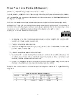
Страница 63: ...er these original settings in the diagram to the right by simply marking an X for UP or DOWN on each switch 1 Activate the Fast Vend Shutoff programming mode by setting Switch 1 ON Switch 2 OFF Switch 3 OFF Switch 4 ON Switch 5 OFF 2 Press the red selection button one time This advances you to the 1st step as per the Country Currency tables below This step sets the maximum quantity of a bill type ...

Страница 64: ...y the Country Currency tables on the previous page 6 Set Switches to next desired choice by viewing the Max Qty Of Bills table on top of this page 7 Press the red selection button to accept the setting and to advance to the Time Period setting 8 View your choices from the Time Period In Minutes table above and make your selection Once you ve made your selection press the red selection button to ad...

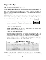
Страница 65: ... 3 Advance to the Error Timeout selection step by setting Switch 1 ON Switch 2 OFF Switch 3 OFF Switch 4 OFF Switch 5 OFF 4 Press the red selection button one time 5 Now set switches to desired setting Choice numbers 1 through 15 as per the cart below Example Set switches to match Choice 5 if you want the Error Timeout feature set to 20 minutes Once you ve made your selection press the red selecti...

Страница 66: ...eature programming mode by setting Switch 1 ON Switch 2 OFF Switch 3 OFF Switch 4 ON Switch 5 ON 2 Press the red selection button one time 3 Advance to the Serial Control Level setting step by setting Switch 1 ON Switch 2 OFF Switch 3 OFF Switch 4 OFF Switch 5 OFF 4 Press the red selection button two times 5 Now set switches to desired setting Choice numbers 1 through 3 as per the cart below Once ...

Страница 67: ...tivate the Power Reset programming mode by setting Switch 1 ON Switch 2 OFF Switch 3 OFF Switch 4 ON Switch 5 ON 2 Press the red selection button one time 3 Advance to the Power Reset selection step by setting Switch 1 ON Switch 2 OFF Switch 3 OFF Switch 4 OFF Switch 5 OFF 4 Press the red selection button three times 5 Now set switches to desired setting Choice numbers 1 or 2 as per the cart below...

Страница 68: ...n one time 3 Advance to the Hold Escrow selection step by setting Switch 1 ON Switch 2 OFF Switch 3 OFF Switch 4 OFF Switch 5 OFF 4 Press the red selection button four times 5 Now set switches to desired setting Choice numbers 1 or 2 from the table below Example Set switches to match Choice 2 if you want the Hold Escrow set to yes Once you ve made your selection press the red selection button one ...

Страница 69: ... UP or DOWN on each switch 1 Activate the Dispenser Transfer programming mode by setting Switch 1 ON Switch 2 OFF Switch 3 OFF Switch 4 ON Switch 5 ON 2 Press the red selection button one time 3 Advance to the Dispenser Transfer selection step by setting Switch 1 ON Switch 2 OFF Switch 3 OFF Switch 4 OFF Switch 5 OFF 4 Press the red selection button five times 5 Now set switches to desired setting...

Страница 70: ... first step is for the tens digit of the forced dispense amount Please note you may set the force dispense amount from 01 to 99 Example Set the switches to match choice number 10 if you want a 0 in the tens digit This would reflect a forced dispense amount less than ten The ones digit in the next step would then determine the forced dispense amount 6 Press the red selection button one time to acce...

Страница 71: ...e by setting Switch 1 ON Switch 2 OFF Switch 3 OFF Switch 4 ON Switch 5 ON 2 Press the red selection button one time 3 Advance to the Forced Dispense Override setting step by setting Switch 1 ON Switch 2 OFF Switch 3 OFF Switch 4 OFF Switch 5 OFF 4 Press the red selection button eight times 5 Now set switches to desired setting Choice numbers 1 or 2 as per the cart below Example Set switches to ma...

Страница 72: ...Feature programming mode by setting Switch 1 ON Switch 2 OFF Switch 3 OFF Switch 4 ON Switch 5 ON 2 Press the red selection button one time 3 Advance to the Accumulate setting step by setting Switch 1 ON Switch 2 OFF Switch 3 OFF Switch 4 OFF Switch 5 OFF 4 Press the red selection button nine times 5 Now set switches to desired setting Choice numbers 1 or 2 as per the cart below Once you ve made y...

Страница 73: ...the Dispenser Type programming mode by setting Switch 1 ON Switch 2 OFF Switch 3 OFF Switch 4 ON Switch 5 ON 2 Press the red selection button one time 3 Advance to the Dispenser Type selection step by setting Switch 1 ON Switch 2 OFF Switch 3 OFF Switch 4 OFF Switch 5 OFF 4 Press the red selection button ten times 5 Now set switches to desired setting Choice numbers 1 through 5 as per the cart bel...

Страница 74: ... Dispenser Sub Type selection by setting Switch 1 ON Switch 2 OFF Switch 3 OFF Switch 4 OFF Switch 5 OFF 4 Press the red selection button eleven times 5 Now set the switches to the desired setting Choice numbers 1 through 3 as per the chart below Once you have made your selection press the red selection button one time Example Set switches to match choice 3 if you want the Dispenser Sub Type set t...

Страница 75: ... Stringing Detection Level Feature programming mode by setting Switch 1 ON Switch 2 OFF Switch 3 OFF Switch 4 ON Switch 5 ON 2 Press the red selection button one time 3 Advance to the Stringing Detection Level setting step by setting Switch 1 ON Switch 2 OFF Switch 3 OFF Switch 4 OFF Switch 5 OFF 4 Press the red selection button thirteen times 5 Now set switches to desired setting Choice numbers 1...

Страница 76: ...each switch 1 Activate the Count Items Out programming mode by setting Switch 1 ON Switch 2 OFF Switch 3 OFF Switch 4 ON Switch 5 ON 2 Press the red selection button one time 3 Advance to the Count Items Out selection step by setting Switch 1 ON Switch 2 OFF Switch 3 OFF Switch 4 OFF Switch 5 OFF 4 Press the red selection button Nineteen times 5 Now set switches to desired setting Choice numbers 1...

Страница 77: ... Bill Acceptor Shutdown programming mode by setting Switch 1 ON Switch 2 OFF Switch 3 OFF Switch 4 ON Switch 5 ON 2 Press the red selection button one time 3 Advance to the No Bill Acceptor Shutdown selection step by setting Switch 1 ON Switch 2 OFF Switch 3 OFF Switch 4 OFF Switch 5 OFF 4 Press the red selection button Twenty times 5 Now set switches to desired setting Choice numbers 1 or 2 from ...

Страница 78: ...oin Acceptor Shutdown programming mode by setting Switch 1 ON Switch 2 OFF Switch 3 OFF Switch 4 ON Switch 5 ON 2 Press the red selection button one time 3 Advance to the No Coin Acceptor Shutdown selection step by setting Switch 1 ON Switch 2 OFF Switch 3 OFF Switch 4 OFF Switch 5 OFF 4 Press the red selection button Twenty One times 5 Now set switches to desired setting Choice numbers 1 or 2 fro...

Страница 79: ...2 Press the red selection button one time 3 Advance to the Like Value Override selection step by setting Switch 1 ON Switch 2 OFF Switch 3 OFF Switch 4 OFF Switch 5 OFF 4 Press the red selection button Twenty two times 5 Now set switches to desired setting Choice numbers 1 or 2 from the table below Example Set switches to match Choice 2 if you want the Like Value Override set to yes Once you ve ma...

Страница 80: ...h 1 Activate the Mylar Note Check programming mode by setting Switch 1 ON Switch 2 OFF Switch 3 OFF Switch 4 ON Switch 5 ON 2 Press the red selection button one time 3 Advance to the Mylar Note Check step by setting Switch 1 ON Switch 2 OFF Switch 3 OFF Switch 4 OFF Switch 5 OFF 4 Press the red selection button Twenty five times 5 Now set switches to desired setting Choice numbers 1 or 2 from the ...

Страница 81: ...ing Switch 1 ON Switch 2 OFF Switch 3 OFF Switch 4 ON Switch 5 ON 2 Press the red selection button one time 3 Advance to the Overpay Timer selection step by setting Switch 1 ON Switch 2 OFF Switch 3 OFF Switch 4 OFF Switch 5 OFF 4 Press the red selection button Twenty six times 5 Now set switches to desired setting Choice numbers 1 or 2 from the table below Example Set switches to match Choice 2 i...

Страница 82: ...ress the red selection button one time This advances you to the 1st Step as per the Country and Bill Denomination Group chart below This first Step is for the tens digit of the bonus token amount for either the U S 1 a Canadian 5 or a Mexican 20 note Please note you may set the bonus amount from 01 to 99 for each denomination COUNTRYand BILL DENOMINATION GROUPS UNITED STATES CANADA MEXICO Steps Pa...

Страница 83: ...gs This will also advance you to the Ones Digit setting for this same denomination 5 Now set switches to desired setting Choice numbers 1 through 10 on the Bonus Token parameter table above Again this sets the Ones Digit setting for the bonus token amount for this bill denomination Example Set the switches to match Choice 4 if you want a 4 in the Ones Digit This will allow for four extra tokens bo...

Страница 84: ... Ones digit can only be set to either 0 or 5 9 Now set switches to desired setting from the Choice numbers 1 through 10 below Multi Denomination Bill Tube Dispensers repeat steps 2 through 9 for each additional cassette or tube up to four cassettes or tubes total For coin changers only program each denomination that will be dispensed 5 10 25 1 00 If all tubes are the same value you only need to pr...

Страница 85: ...G SWITCH POSITIONS SW2 SW3 SW4 SW5 1 1 DOWN DOWN DOWN UP 2 2 DOWN DOWN UP DOWN 3 3 DOWN DOWN UP UP 4 4 DOWN UP DOWN DOWN 5 5 DOWN UP DOWN UP 6 6 DOWN UP UP DOWN 7 7 DOWN UP UP UP 8 8 UP DOWN DOWN DOWN 9 9 UP DOWN DOWN UP 10 0 UP DOWN UP DOWN ...

Страница 86: ...u will be setting a 5 4 Press the red selection button one time This advances you to the next value digit 5 Now set switches to desired setting from the Choice numbers 1 through 10 below 6 Press the red selection button one time This advances you to the next value digit 7 Now set switches to desired setting from the Choice numbers 1 through 10 below 8 Press the red selection button one time This a...

Страница 87: ...witch 2 OFF Switch 3 OFF Switch 4 OFF Switch 5 OFF 3 Press the red selection button eight times This advances you to the correct step step 9 4 Now set switches to desired setting from the Choice numbers 1 through 9 below 5 Press the red selection button one time 6 End the programming sequence by resetting the switches to the OFF down position and then press the red selection button one time to put...

Страница 88: ...FF Switch 3 OFF Switch 4 OFF Switch 5 OFF 3 Press the red selection button nine times This advances you to the correct step step 10 4 Now set switches to desired setting from the Choice numbers 1 through 9 below 5 Press the red selection button one time 6 End the programming sequence by resetting the switches to the OFF down position and then press the red selection button one time to put the mach...

Страница 89: ...ce numbers 1 through 10 below 4 Press the red selection button one time This advances you to the Tens digit of the count amount 5 Now set switches to desired setting from the Choice numbers 1 through 10 below 6 Press the red selection button one time This advances you to the Ones digit of the cents amount 7 Now set switches to desired setting from the Choice numbers 1 through 10 below 8 Press the ...

Страница 90: ...N OFF on each switch 1 Activate the Bin Low Override Feature programming mode by setting Switch 1 ON Switch 2 OFF Switch 3 ON Switch 4 ON Switch 5 ON 2 Press the red selection button one time 3 Advance to the Bin Low Override Feature setting step by setting Switch 1 ON Switch 2 OFF Switch 3 OFF Switch 4 OFF Switch 5 OFF 4 Press the red selection button three times 5 Now set switches to desired set...

Страница 91: ...EE ...

Страница 92: ...d Home Office P O Box 36550 Indianapolis IN 46236 0550 3130 North Mitthoeffer Road Indianapolis IN 46235 0550 317 899 6966 800 968 6955 FAX 317 899 6977 WEB www standardchange com Record these numbers here for use when ordering parts Serial _______________________ Model _____________________ ...

Отзывы: