


EN
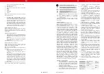
SOLDERING IRON OPERATION
1.
Device must be placed on stable work table,
soldering iron must be placed into the holder.
2.
Fix the appropriate soldering tip and connect the
device to the power source.
5.
Too high temperature of the soldering iron may be
the cause of reduction of the functionality of the
soldering tips.
6.
Soldering iron tip must be cleaned regularly using
sponge and plate on a layer of tin to prevent tips
oxidation.
9
Rev. 18.09.2017
EN
USAGE PURPOSE
The device is designed for:
1.
Different kind of soldering, de-soldering of the
electronic components such as: SOIC, CHIP, QFP,
PLCC, BGA, SMD, etc.
2.
Shrinking, paint drying, adhesive removal, thawing,
warming, plastic welding.
3.
Power supply in scope of scientific research, product
development, laboratories, etc.
Any damage resulting from a non-conform use of the
device is payable by the user!
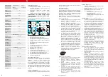
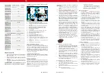
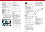
PRINCIPLE OF OPERATION
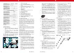
Assembly
1
19
2
3
4
5
6
7
8
17
16
15
14
13
12
11
9
10
18
1.
HOT AIR turn on/off switch
2.
HOT AIR temperature display
3.
HOT AIR temperature set buttons
4.
Power supply voltage reading display
5.
Power supply voltage adjustment knob
6.
Power supply current reading display
7.
DC power supply switch on / off
8.
USB socket
9.
Switch between output / input voltage
10. In-use control light
11. Connection test voltage (+)
12. Ground connection
13. Connection metering voltage (+)
14. Soldering iron connection socket
15. Air flow volume adjustment knob
16. Hot air gun operating mode selection button.
17. Soldering iron temperature set buttons
18. Soldering iron temperature display
19. Soldering iron turn on / off switch
BEFORE FIRST USE
Upon receipt of the goods, check the packaging for
integrity and open it. If the packaging is damaged, please
contact your trans¬port company and distributor within 3
days, and document the damages as detailed as possible.
Do not turn the package upside down! When transporting
the package, please ensure that it is kept horizontal and
stable. Please keep all packaging materials (cardboard,
plastic tapes and styrofoam), so that in case of a problem,
the device can be sent back to the service centre in accurate
condition.
DISPOSING OF PACKAGING
The various items used for packaging (cardboard, plastic
straps, polyurethane foam) should be conserved, so that
the device can be sent back to the service center in best
conditions in case of problem!
INSTALLING THE APPLIANCE
Appliance location
The work surface where the device will be located must be
suitable for the size of the appliance, please refer to the
measurements.
The work surface must be levelled, dry, heat-resistant and
at a fitting height from the ground to enable a proper use
of the device.
The power cord connected with the appliance must be
properly grounded and correspond to the technical details.
SMD REWORK STATION
1.
Device must be placed on stable work table, HOT AIR
gun must be placed into the holder.
2.
Fix the appropriate nozzle and connect the device to
the power source
3.
Turn on the device with the main switch placed at
the back of the device, turn on the HOT AIR gun with
switch (1), gun will start to heat.
4.
Using buttons (3) set the desired temperature, the
display (2) will show this temperature for a moment
and then it will show the actual temperature of the
gun. After temperature stabilization, desired air flow
volume can be adjusted by knob (15).
5.
After work, gun should be placed into the holder.
Heating will stop and gun will start to cool down.
If the tempera¬ture value will be lower than 100°C,
the display (2) will show “---“ and the device will be
in “stand by” mode. OPERATING MODE SELECTION:
Use the switch (16) to select auto / manual hot air
gun operating mode. In the auto mode, heating
switches off automatically once the gun is replaced
into the holder and it goes into a stand-by mode.
In the manual mode, the gun heating is permanent.
6.
If the device is not using for a long time, it should
be completely disconnected from the power source.
7.
NOTE: It is forbidden to cover the air intake holes
on the handle of a SMD rework gun during work.
This may cause serious damages of the fan and the
heater!
8
Rev. 18.09.2017
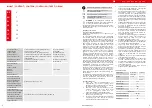
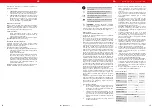
Product name
Soldering station
with magnifying
lamp
Soldering
station
Voltage stability
with load
<0.01 ±2mV
TEmperature
coefficient
[ppm/°C]
< 300
Ripple noise
<1mV RMS
3.
Turn on the device with the main switch placed at the
back of the device, turn on the soldering iron with
switch (19), it will start to heat.
4.
Using buttons (17) set the desired temperature, the
display (18) will show this temperature for a moment
and then it will show the actual temperature of the
soldering iron.
5.
After work, soldering iron should be placed into the
holder and turned off by switch (19).
DC POWER SUPPLY OPERATION
1.
Device must be placed on stable work table; connect
the device to the power source.
2.
Connect the load to the appropriate terminals (+)
and (-).
3.
Set the output voltage value using knobs (5).
4.
DC voltage testing:
a. Connect leads to sockets (11) and (12)
b. Press button (9)
c. Connect the load to the wires.
d. ATTENTION! Range of work in this mode is
0 to 50V DC!
GENERAL REMARKS
1.
If the display is showing the „---„ it means that
the output temperature is lower than 100°C, SMD
Rework Station is in stand by mode, HOT AIR gun is
placed in the holder.
2.
If the display is showing “S-E” it means that soldering
iron is disconnected, and HOT AIR gun is having
problem with the heat sensor.
3.
When the device is being turned on, both soldering
iron and HOT AIR gun should be placed in their
holders.
4.
The outlet of the HOT AIR gun should be clean and
free from any obstacles.
5.
When using small nozzles, it should be remembered
that the air flow should be suitable to the diameter
of the fixed nozzle. In order to avoid any HOT AIR
gun damages, too high air flow along with the high
temperature mustn’t be used for a long period of
time.
6.
Depending on user’s needs, different air flow
settings may cause slight variations in temperatures
value. The mini¬mum distance between the outlet of
the HOT AIR gun and the subject is 2 mm.
7.
Good ventilation of the room in which the appliance
is used must be provided. In addition, the device
should be placed in a location with good air
circulation to dissipate heat.
SAFETY ISSUES REMARKS
1.
Nozzles should be installed without the use of
excessive force, also do not use the pliers or
tweezers. Do not over tighten the mounting screws
of the nozzle.
2.
Tips and nozzles can be changed when the HOT AIR
gun and the soldering iron are completely cold.
3.
It is forbidden to use the device near the flammable
or combustible elements and objects or at similar
places. Tips and nozzles as well as the air coming out
of the HOT AIR gun have very high temperature, it
is forbidden to touch these elements as well as it is
forbidden to put the hot air directly to face or body.
This can cause serious burns.
4.
After long time of use, the outlet of HOT AIR gun
may be covered with some dust. The outlet should
be cleaned on a regular basis in order to ensure
undisturbed air flow.
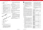
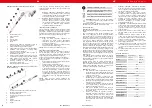
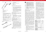
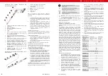
REPLACEMENT OF HOT AIR REWORK HEATING ELEMENT
1.
HOT AIR gun covers
2.
Element of the handle
3.
Heater
4.
Heater cover
5.
Outlet pipe
6.
Nozzle
1.
Before heater replacement make sure that the HOT
AIR gun is completely cold.
2.
Remove the screws in the gun covers.
3.
Unscrew the element of the handle (2) and take off
the gun covers.
4.
Gently remove the fan and remove the wire board
screws.
5.
Disconnect the heater from the wire board (pay
attention to the wires connection order).
6.
Remove the heater from the housing, pay attention
to the steel grounding wire.
7.
New heater should be wrapped with new mica paper
and then it should be placed inside the housing.
8.
Connect the wires to the board in accordance with
their original connection method.
9.
Fix the gun in reverse order.
6
5
4
3
2
1
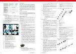
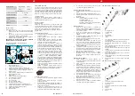
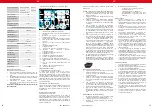
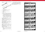
REPLACEMENT OF THE SOLDERING IRON TIP AND
SOLDERING IRON HEATING CORE ELEMENT
1
2
3
4
5
6
7
8


