


Mounting and installation
Operating Instructions ET-xx8 / MT-xx8
R. STAHL HMI Systems GmbH / OI_ET_MT-xx8_en_V_01_02_03.docx / 10.03.2021
Page 43 of 84
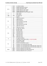
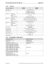
8.5.8
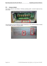
Electric connections of interfaces X1 ... X9 and X31 ... X35
Stripping length
7
mm
Mounting torque
0.5 ... 0.6
Nm
Connectable conductor cross section
rigid
0.2 ... 2.5 (24 ... 12)
mm² (AWG)
flexible
0.2 ... 2.5 (24 ... 12)
mm² (AWG)
Multi-conductor connection
(two conductors with the same cross section and conductor type)
rigid
0.2 ... 1.5 (24 ... 16)
mm² (AWG)
flexible
0.2 ... 1.0 (24 ... *1)
mm² (AWG)
Multi-conductor connection for X1 as screw terminal
(two conductors with the same cross section and conductor type):
rigid
0.2 ... 1.5 (24 ... 16)
mm² (AWG)
flexible
0.2 ... 0.75 (24 ... 18)
mm² (AWG)
* No direct equivalent AWG size listed in IEC 60079-7.
Notes on plug and screw connectors:
The plug connectors are designed to be readily connected or disconnected without load.
Tighten the plug connector screws.
Ensure that the following maximum rated current values are not exceeded:
o
The maximum rated current value for every contact of the X1 plug connector is 12 A.
o
The maximum rated current value for every contact of the X1 screw connector is 16 A.
Values that must not be exceeded at the place of installation:
o
Voltage: max. 250 V
o
Short-circuit current: max. 1500 A
Only use copper wires with the following characteristics for connections to the device:
o
For ambient temperatures <60 °C: copper wires approved for at least 90 °C
o
For ambient temperatures >60 °C (up to permitted maximum temperature): copper wires
approved for 105 °C
Observe and apply tightening torques recommended for connection terminals.
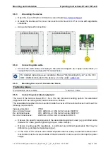
8.5.9
Details for electrical connection of Interface X10
Use connector X10 with connectors / devices approved by the manufacturer only.