Operating Instructions ET-xx8 / MT-xx8
Appendix B
Page 60 of 84
R. STAHL HMI Systems GmbH / OI_ET_MT-xx8_en_V_01_02_03.docx / 10.03.2021
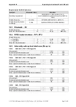
18.2.4
X33 / X34
– USB KB/M
X33 / X34
– USB KB/M ter (X33/34-1), D- (X33/34-2), D+ (X33/34-3), GND (X33/34-4):
Max. output voltage
U
o
=
5.36
VDC
Max. output current
I
o
=
249.85
mA
Max. output power
P
o
=
0.518
W
Trapezoidal output characteristics
Max. external
capacitance
C
o
=
65
46
32
25
21
µF
Max. external inductance
L
o
=
0.68
1.68
2.68
3.68 4.68
µH
C
o
and L
o
pairs directly above / underneath each other may be used.
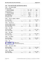
18.2.5
X35
– USB
X35
– USB ter (X35-1), D- (X35-2), D+ (X35-3), GND (X35-4):
Max. output voltage
U
o
=
5.36
VDC
Max. output current
I
o
=
1.264
A
Max. output power
P
o
=
2.949
W
Trapezoidal output characteristics
Max. external
capacitance
C
o
=
65
44
30
23
19
µF
Max. external inductance
L
o
=
0.68
1.68
2.68
3.68 4.68
µH
C
o
and L
o
pairs directly above / underneath each other may be used.
18.2.6
X36 / X37
– RF1 / RF2
X36 / X37
– RF1 / RF2, Typ W02, W05, W22, W55, W25 per circuit:
Radio frequency
f
o
=
2.4 … 5
GHz
Max. RF threshold power
P
o
=
17 (50)
dBm (mW)
Calculating the RF threshold power
Make sure that the RF threshold power radiated from the antenna does not exceed 33 dBm
(2 W) for Gas Group IIC.
The calculation of the threshold power should take into account the output power of the
interface and the gain of the antenna. Any losses from the cable can also be included in
this calculation.
Example of RF threshold power calculation:
Output power of the interface X36 / X37
17 dBm (50 mW)
Coaxial cable power dissipation
2dB
Antenna gain
5 dBi
RF threshold power radiated from the antenna =
17 dBm
– 2 dB + 5 dBi = 20 dBm (100 mW)
In this example, the coaxial cable and the antenna comply with the requirements of Gas Group
IIC, since 20 dBm (100 mW) <33 dBm (2 W).

