STA-RITE SR-2700 Скачать руководство пользователя страница 3

3

INTRODUCTION

The 

SR–2700

is a programmable controller for commercial

swimming pool filters which allows very detailed control
that can be modified by the operator. This programming
guide introduces and describes all the available windows
and menus of the SR–2700, from navigating and initializing
the windows to programming and customizing specifica-
tions. Please read carefully and take notice of all 

WARN-

INGS

and 

Notices

to ensure safe operation. If there are any

questions after reading through the guide, please call your
local STA-RITE dealer or call STA-RITE directly. 

INITIALIZING THE SR–2700 (Figures 1 and 2)

When initializing the 

SR–2700

, it will perform a brief check

of its internal system and set up the memory for operation.
The 

SR–2700

window will open a window (Figure 1) show-

ing the model type, the current status and all connected
modules (including communication, memory and remotes
(External RAM, modem and printer)). If these items are
detected they will be configured to operate; if not, they will
be disabled. 

NOTE

: If a module was previously installed but is not

detected, the window will display the message: “WARN-
ING: External ram not detected”. 
Once this check is complete, the window will then open to
the STA-RITE Information window (Figure 2). Touch this
window anywhere with the stylus to continue to the main
menu. If not touched, the Controller will automatically
cycle to the 

Readings

window.

At the top of the face of the controller, above the digital
window, you will see two groups of red numbers. These
numbers change every two seconds between a)Influent and
Effluent Pressure and b)pH and ORP. The appropriate mea-
surement is indicated by an LED light.

WINDOW NAVIGATION

This section introduces “Window Navigation”, with guide-
lines to allow customizing window display options, entering
values and programming. 
The 

SR–2700

has a Graphical User Interface (GUI) similar

to “Windows”, but with only one window displayed at a
time. The user interface is a touch-panel display, which
gives access to most of the controller’s functions and set-
tings through a series of menus, sub-menus and buttons.

NOTE:

In this text guide, system menus will be indicated in

BOLD CAPITAL LETTERS

and sub-menus will be in 

Bold

Regular Letters. 

On-window buttons will be displayed in

Bold Italic Letters.

Operate the SR–2700 touch-panel display with a plastic sty-
lus (or other non-marking instrument). When operating the
touch-panel display, hold the stylus as you would an ordi-
nary pen, being careful not to touch the display with your
fingers. Do not exert pressure when using the stylus, as the
panel will respond to a light touch. 

NOTE: 

Using a pen or other sharp object could damage the

display. Do not exert pressure; the display will respond to a
light touch from the stylus. Excessive pressure could dam-
age the display and will void the warranty. To keep display
free of fingerprints, avoid touching it with your hands.

Selecting Items

There are three ways to select menu items on the interface. 
1. Touch the menu item directly on the window. The

selected item will open another window to offer more
options.

2. Directly touch the on-window Buttons. The selected

button will open another window, which offers more
options, or will toggle to a different state.

3. Use the directional arrow keys to navigate through the

items (not all windows have arrows). The arrow keys
will usually highlight the selected item. Some windows
have directional arrow keys on the top of the window
which will allow you to change windows.

NOTE:

Use the small 

x

on the top right-hand corner of

the window to back out to the previous window.

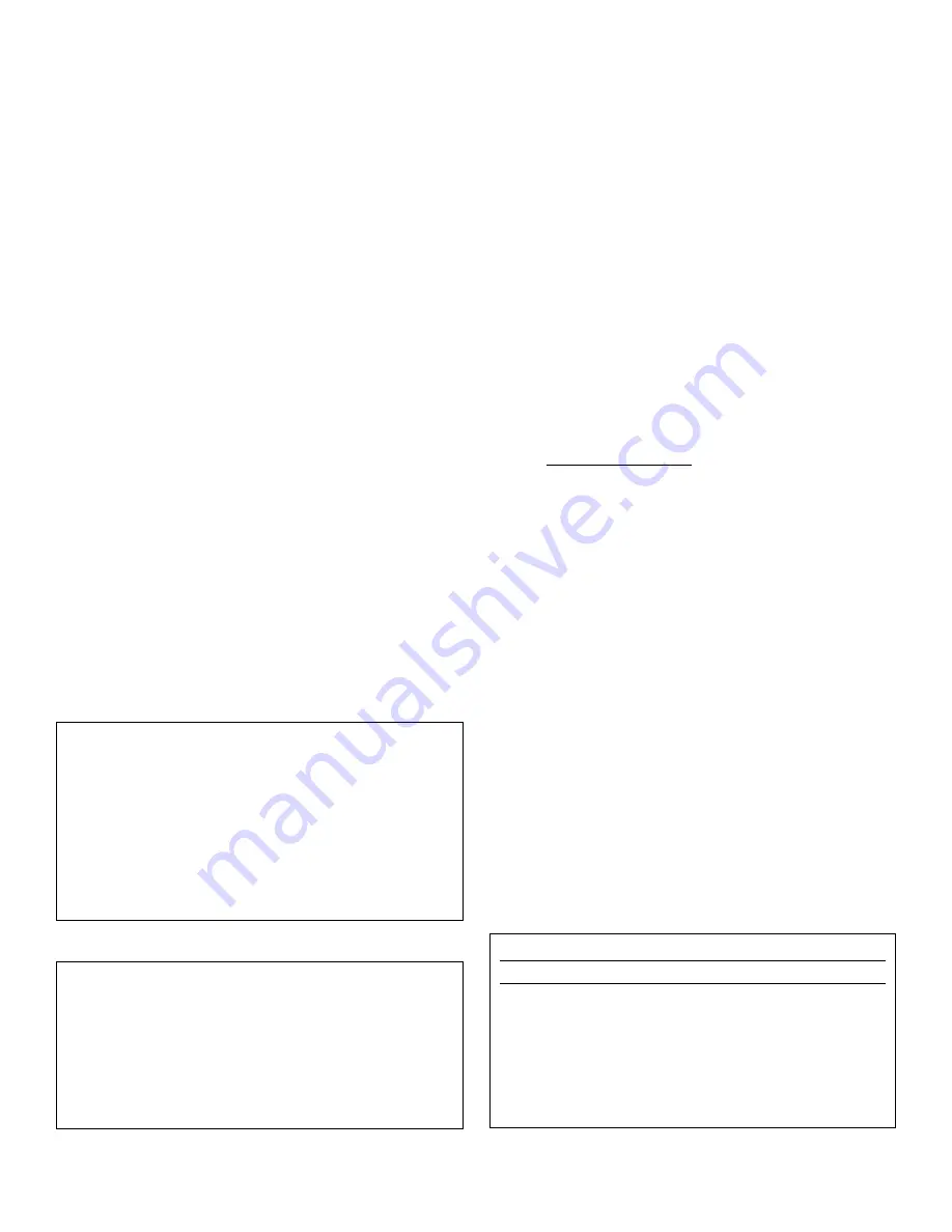
Changing Items (Figure 3)

NOTE:

There is no ‘undo’ function. Once a change is made,

the only way to change it back is to re-enter the original
value.

Figure 1

Model SR–2700R6

11-13-01

Backwash CL
Initializing

Ext RAM Detected
High speed modem detected
Printer installed

STA-RITE Backwash Control System
293 S. Wright Street    
Delavan, WI 53115    
(800)752-0183  
F(800)582-2217

Figure 2

Press to Toggle Window

d

I

Enter Value  (#.##)               

- > -

Q   W   E   R   T   Y   U   I   O   P   <   &

7   8   9

A   S   D   F   G   H   J   K   L   :   -   =

4   5   6

Z   X   C   V   B   N   M   ,   .   /   #

1   2   3  

Cancel     Space     Enter     

0  . 

Figure 3

Содержание SR-2700

Страница 1: ...ol Spa Group 293 Wright Street Delavan WI 53115 North America 800 752 0183 FAX 800 582 2217 International 262 728 5551 FAX 262 728 4461 TELEX ITT 4970245 www sta ritepool com Union City TN Delavan WI Mississauga Ont Murrieta CA Printed in U S A 2002 Sta Rite Industries Inc S612 2 20 02 ...

Страница 2: ...ns to the controller Do not remove the controller s front panel if the supply power is connected to the controller Chemical burn hazard if chemicals feed at no flow See Programming pH Page 21 8 for details CONTENTS Safety 2 Introduction 3 Initializing the SR 2700 3 Window Navigating 3 Selecting Items 3 Changing Items 3 Main Menu 4 Readings 4 Data 4 MPS Timers 5 Information 5 Manual 6 Password 6 Pr...

Страница 3: ...face is a touch panel display which gives access to most of the controller s functions and set tings through a series of menus sub menus and buttons NOTE In this text guide system menus will be indicated in BOLD CAPITAL LETTERS and sub menus will be in Bold Regular Letters On window buttons will be displayed in Bold Italic Letters Operate the SR 2700 touch panel display with a plastic sty lus or o...

Страница 4: ...ed in any order When the flow switches are enabled in the programming they allow chemical feed while there is flow but prevent feed at no flow Disable the flow switch in the program ming to allow chemical feed at no flow The Flow Window displays the following ITEM Sensor names MEAS Current measurement reading The Overfeed box follows this number An o in any box indicates that that relay is in over...

Страница 5: ...ed ON since it was last cleared DAY COUNT Not used Information Figure 8 The INFORMATION Window displays important details regarding the status of the SR 2700 listed as follows Software Version The current software revision number and the date the software was updated Power ON Cycles Displays how many times the power has been turned ON or OFF Total Hours ON Displays the total hours the SR 2700 has ...

Страница 6: ...rectly controlling the relays Relays not installed can be used as expansion MPSs SOFT RELAYS The soft relays are software relays not mechan ical relays Up to 14 soft relays or expansion relays are used to increase the capabilities of the mechanical relays when more detailed control is required You can have from 1 to 14 soft relays depending on how many relays are actually installed ALARMS There ar...

Страница 7: ...t the sensor manufacturer s guide for more infor mation on calculations NOTE The lower the K factor the higher the flow will be To calibrate the Digital Flow sensor touch the on window button Change and enter the flow constant K factor on the keyboard touch Enter Return to the Calibrate Flow menu The change will be record ed along with the sensor flow reading at the time the calibra tion was made ...

Страница 8: ...ard 2 Touch Enter 3 The window will return to the Calibrate ORP menu dis playing the entered measurement 4 Touch OK The change will be recorded along with the sensor reading at the time the calibration was made NOTE Touch Reset to clear the calibration on this sensor Example The default set point is 700 the measured PPM is 0 5 1 5 PPM is desired and the current display shows a measurement of 710 m...

Страница 9: ...l described in the following pages Use the directional arrows to highlight the settings Touch the Change button to offer choices or to access keyboard input These settings must be entered correctly as they are impor tant for calculating correct readings and troubleshooting Global Alarm Sets the percentage above or below the set point that will trip the alarm This can be disabled in the programming...

Страница 10: ...ed below It also has multiple windows accessible by a variety of buttons which offer more features When setting up Communication for the first time enter the following settings Use directional arrows to highlight the settings and touch the Change button to toggle through choices or to access the keyboard input window Rings to answer on The number of rings required before the SR 2700 will answer th...

Страница 11: ... operators to particu lar alarm conditions Touch NEXT 4 to display more pager numbers System Figure 26 The SYSTEM window contains both important data details listed below and buttons allowing access to more win dows offering more features This section explains each of these windows and how to navigate through them in order to program various devices When using the controller for the first time the...

Страница 12: ...ssure minus the low P2 or effluent pressure Flow Fl 1 Fl 2 Fl 3 These inputs are general purpose inputs which can be used either as switches or with flow inputs NOTE Connect the flow inputs only to sensors or devices that do not supply voltage NEVER CONNECT FLOW INPUTS TO DEVICES THAT SUPPLY VOLTAGE ORP The oxidation reduction potential measurement of the water This measurement is used in the calc...

Страница 13: ... has access to the service menu only In this menu the service personnel may calibrate or manually turn on relays but not change the programming There are up to three passwords at this level allowing different pass words for different people Disable Figure 31 The Global Disable feature is used to turn OFF any MPS group for the time period specified on the page Select the desired MPS group by touchi...

Страница 14: ...f needed SEQ The sequence number s if any associated with this command Each command will be valid only when operat ing in the sequence s associated with it Up to four sequences may be specified for each command See Normal CMD or Sequence CMD below The D and I buttons bottom right of window allow com mands to be deleted or inserted When the command is touched D or I will be displayed between the ar...

Страница 15: ... and Sequence Command Specify the sequence then set up that sequence s associated commands Change Control Command x COMMAND Sequences ON VALUE 7 50 SEQUENCES 1 2 3 4 SEQUENCES CMD OK Figure 34 TROUBLESHOOTING This section lists common problems with the most likely solution IMPORTANT If any problems remain after reading the guides and troubleshooting procedures please call Sta Rite direct ly at 1 8...

Страница 16: ...e Sel Spec Command to Change Change Control Command Calibration Select to Calibrate Calibrate Flow Calibrate pH Calibrate ORP Cal Calculated PPM Calibrate Temperature General General Setup Data Setup Modem Pager Test Pager s System System Menu MPS Wizard Select MPS Module Select MPS to Configure Select New Configuration Security Display Reset Menu Sensor Disable APPENDIX A MENU TREE See Pages 21 a...

Страница 17: ...ited by Health Dept requirements often to 100 PPM Table for Pools Minimum Ideal Maximum Free Chlorine PPM 1 0 1 0 3 0 3 0 Combined Chlorine PPM None None 0 2 Bromine PPM 2 0 2 0 4 0 4 0 pH 7 2 7 4 7 6 7 8 Total Alkalinity PPM 60 80 100 180 TDS PPM 300 1 000 2 000 3 000 Calcium Hardness PPM 150 300 400 500 1000 Cyamuric Acid PPM 10 30 50 150 Table for Spas Minimum Ideal Maximum Free Chlorine PPM 1 ...

Страница 18: ...ompute it first ON If Alarm ON The selected module indicates which alarm this is based ON OFF If Alarm ON The selected module indicates which alarm this is based ON ON If Overfeed 1 x 24 The MPS will turn ON if the overfeed timer has been reached for the indicated MPS ON If SET ALRM 0 x 24 The set point alarms are calculated from the alarm percentage The MPS will be ON if the indicated set point a...

Страница 19: ...s less the ON time will be linearly scaled down to less time 4 The set point is 7 5 When the pH is greater than 7 5 the MPS will be ON The following commands will modify this ON condition If there were no more commands this MPS would be ON as long as the pH was greater than 7 5 5 This command will calculate the maximum and minimum times that the relay should be ON As the current reading approaches...

Страница 20: ...Description 1 ON Sequences Turns ON the sequence the commands are using 2 Manual ON Time 00 02 00 The time that the relay stays ON when manually turned ON 3 ON if Temp 76 9 The temperature set point 4 Min Time ON 00 02 00 Turns the relay ON or if the relay is turned ON by another relay it will stay on at least this long 5 Min Time OFF 00 02 00 The minimum amount of time before the heater will turn...

Страница 21: ... x System Menu Security Reset Menu Display MPS Wizard Change Sensor See Page 24 General Setup Data Setup Modem Change See Page 24 Manually Toggle MPS Select MPS Module Password Timers Enter password on keyboard Programming pH ORP Flow Keyboard Change x Info More Backwash Cycle On Flow 1 Backwash Info Flow 2 Flow 3 Model SR2700 Programmable Control Initializing Model SR2700 Programmable Control Ini...

Страница 22: ...d Keyboard Use arrows to select sensors toggle Change to show whether sensor is installed or not Installed Sensors Change Use arrows to select sensors toggle Change to show whether sensor is installed or not Installed Sensors Change Change Rly Measure Display Setup Use Arrows to Select Items To Display use Keyboard to change relay number Display Reset Menu Use arrows to select relays to change Key...

Страница 23: ...23 ...

Страница 24: ...24 ...

Отзывы: