


10
Data Setup (Figure 21)
The
Data Setup
button located in the lower left corner of
the
General Setup
window accesses the following list of
items, plus the
Sensors
button (all described in the follow-
ing pages). Use directional arrows to highlight the setting
and touch the
Change
button to access keyboard input.
Time Spacing:
The amount of time between recordings. The
range is from two seconds to eighteen hours.
NOTE:
This is the only value in this window which can be
changed.
% Used:
The percentage of the data memory filled.
Number of Days:
This number is automatically changed
based on the time spacing. When the time spacing is
changed the SR–2700 will calculate how many days of data
the memory can hold and display it here.
Line:
The line the controller will record next. The SR–2700
has 3300 lines. When the data is filled up the SR–2700 will
delete the oldest line to make room for the new data.
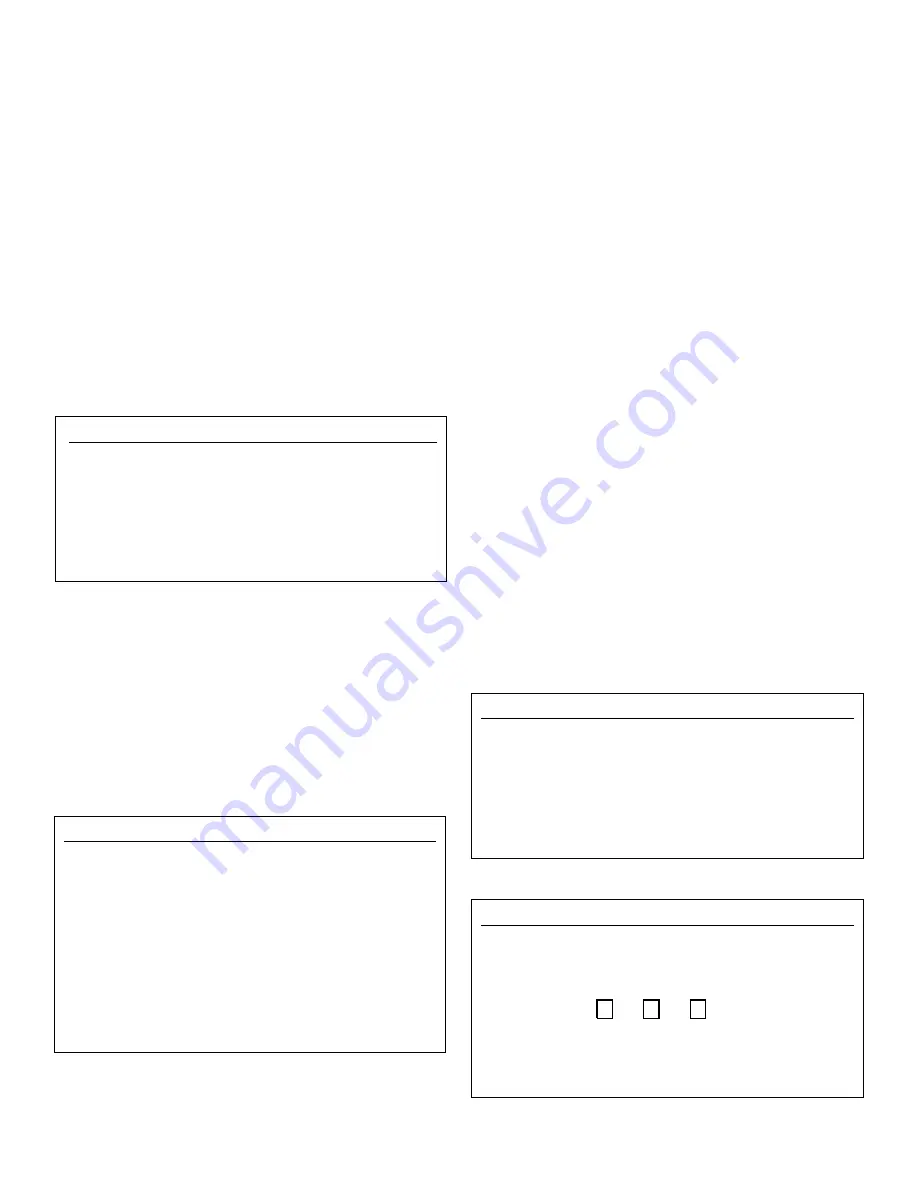
Sensors (Figure 22)
Touching the
Sensors
button, located in the lower left corner
of the
Data Setup
window, will open the
Sensor to Display
window. This window allows the selection of sensor measure-
ments to be displayed when viewing the data. The selections
have no effect on the data being recorded, only the data to be
displayed. Use the directional arrows to highlight the sensor
checkbox for each sensor. Touching the
Change
button in the
lower right hand corner of the window selects, or unselects,
the sensor box highlighted for each module.
Communication (Figures 23 and 24)
Access the
Communication Setup Menu
from the
General
Setup Menu
by pressing the
Modem
button at the bottom of
the window. This window contains important data details
listed below. It also has multiple windows accessible by a
variety of buttons, which offer more features.
When setting up ‘Communication’ for the first time, enter
the following settings. Use directional arrows to highlight
the settings and touch the
Change
button to toggle through
choices or to access the keyboard input window.
Rings to answer on:
The number of rings required before
the SR–2700 will answer the call. The answering range is
from one to nine rings (1-9); 0 disables answering.
Long Hang-up Time:
Specifies the length of time that the
SR–2700 will ignore incoming calls when AcuCOM uses
the ‘Long Hang-up’ command. This command allows
AcuCOM to call other controllers on the same line.
Sync Bytes:
These must match the sync bytes in AcuCOM
for communication to be established. Since AcuCOM is a
freely distributed software package, without this command
in place others could call the controller and see the read-
ings. Using the sync bytes prevents all unauthorized access.
More:
Pressing this button will access
Modem Advanced
Diagnostics
(Figure 24). Technical Support may ask for
information from this window.
Status:
Modem status
Timer:
Modem time
CMD:
CMD (Command) status
From Modem:
Modem initialization string
To Modem:
Sending string (pager/voice numbers)
Reset:
Resets timer and status. Resets and initializes the
modem.
Data Setup
x
Time Spacing
04:00:00
% used
13.1
Number of Days
385
Line
2315
Relay ON Times Line
2
SENSORS CHANGE
Figure 21
Sensor to Display
x
pH
ORP
PPM
Temp
Switch 1
Switch 2
Switch 3
P1
P2
DP12
P3
CHANGE
Figure 22
Communication Setup
-more-
x
Ring to Answer On
:1
Long Hang Up Time
:00:30:00
Sync Byte 1:
0
Sync Byte 2:
0
Pager Test
Pager #’s
CHANGE
Figure 23
Modem Advanced Diagnostics
x
Status:
32 PagDelay :
0
Timer: 9056 PagDelay :
0
CMD :
0 PagStatus :
0
From Modem:
11.1 9600,3360 O OK O OK O
To Modem:
Reset Levels – 112dBm, Q= 0
Figure 24


