background image

6

English

Application

Electronic key reading module with 
MIFARE DESFire EV1/2 technology 
as contactless access control system 
with function LED. Compatible with 

the new EK/EKC 600-… electronic 

keys or cards.

Transponder

Compatible keys are:
• 

EK 600-0 

Electronic key

• 

EKC 600-0 

Electronic key card

Electrical voltage

Mounting, installation and servicing 
work on electrical devices may only 
be performed by a suitably qua

lified 

electrician.

Remarks

• If the Electronic key is attached to 
a set of car keys, this can interfere 
with your car immo-bilizer, as some 
immobilizers work at the same fre-
quency. For this reason, we advise 
not attaching your Electronic Key to 
the same key ring as your car key.
• 

Magnetic fields can pose a 

hazard for pacemakers, magnetic 
data storage media and electronic 
devices. A safe distance must be 
maintained.
• The unit can be operated in the 
following countries:
AT, BE, CH, DE, DK, ES, FI, FR, GB, 
GR, IT, IS, NL, NO, PT, SE.
• Avoid direct sunlight/prolonged 
exposure to heat. Observe the per-
missible temperature range.

Range

The conductor network laid 
throughout the entire Vario bus 
must not excee

d 2000 m. The loop 

resistance (forward and return line 
between the functional unit and 
the control unit) must not exceed 

20 Ohm. A core diameter of 0.8 mm 

results in a range of app

r. 260 m. 

The power supply to the Vario 
Bus components is provided by a 

separate

 transformer TR 602-…/

TR 603-…

Steps must be taken to ensure that 
the supply voltage never exceeds 
9

 V AC at any device 

with maximum 

current consumption.

1 Connection pcb 

For surface mounted door stations: 
Connection not via connection pcbs 
but in a similar manner as Siedle 
Vario using terminal blocks. 

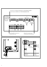
Terminal assignment

bv, cv

Pow

er supply 12 V AC

Da, Db

Vario bus

S1, S2

n.

o. contact 24 V, 2 A

Mounting and installation

Address setting

In order to change the Vario bus 
address, the pre-mounted function 
unit must be removed from the 
mounting plate. See product infor-
mation for the door station. 

Terminal plan for standalone 

operation

Terminal diagram access control 

with EC 602-…


Terminal diagram access control 

with TCIP 603-…


Servicing

The functional unit can be com-
pletely exchanged if required. 
Information regarding replacement 
and checking the functional units 
can be found in the product infor-
mation for the door station. 
During stand-alone operation, all 
keys must be re-read in after an 
electronic key reading module is 
replaced. 

Specifications

Op

erating voltage: 12 V AC or 

12–30 V DC

Operating current: ma

x. 120 mA or 

max. 50 mA

Contact type: co

ntact 24 V, 2 A

Prot

ection system: IP 54

Ambient temperature: 

–20 °C to +55 °C

Commissioning

Vario bus operation 

During bus operation, the input/read 
devices of the different access points 
are linked to one another via a cen-
tral device (controller). 
The key is read in during program-

ming via the EC 602-… or the 
TCIP 603-…


Detailed information can be found in 

the EC 602-… programming instruc

-

tions or TCIP 603-… manual.


Stand alone operation

During stand-alone operation, each 
input/read device is operated alone. 
Used in stand-alone operation, 
the ELM manages a maximum of 
9 users (Electronic-Key EK and/
or Electronic-Key Card EKC) plus a 
master card.
User keys EK/ user cards EKC must 
be read in at the ELM units at which 
they are required to trigger func-
tions. This reading process is initiated 
and terminated with the master 
card.

Procedure:
Reading in the master card

After completion of installation and 
switching on the system, a red LED 
lights up at the front of the ELM. 
Th

e ELM is ready for t

he reading 

process. 

The first user card 

EK/EKC 

read into the

 ELM is automaticall

defined as the mas

ter card, and can 

be used to terminate the reading 
process at any time or to restart a 
new reading process. Make sure 
that the master card is kept in a safe 
place after completion of program-
ming. 
• Hold the EK/EKC up to the ELM. 
The master card has been success-
fully read in. The ELM is automati-
cally switched to the service mode. 
This is signalled by a green LED. 

Содержание Siedle Steel SELM 600-0

Страница 1: ...ectronique Opuscolo informativo sul prodotto Lettore Electronic Key Productinformatie Electronic Key Lezer Produktinformation Electronic Key l ser Produktinformation Electronic Key l sare Informaci n...

Страница 2: ...RM SFPM SCOM SDRM SELM SFPM Br cke link SATLM Br cke link SCOM SELM A A A Vario Bus 222728 D2 D1 c1 b1 Db Da cv bv bc cv Da Db Verbindung zu Installationsleiterplatte SCOM SDRM SELM SFPM Connection to...

Страница 3: ...io Bus Vario bus 230 V AC TR 602 TR 603 230 V AC EC 602 Relais 1 Relay 1 T 12 V AC min 20 Ohm 4 LAN Da M M M M Relais 1 Relay 1 Db Da cv bv Db c b N L1 N L1 N L1 SELM 600 SELM 611 TR 602 TR 603 TR 602...

Страница 4: ...muss die vormontierte Funktions einheit von der Montageplatte abgenommen werden Siehe Produktinformation zur T rstation 3 Anschlussplan f r den Stand Alone Betrieb 4 Anschlussplan Zutrittskontrolle m...

Страница 5: ...nach leuchtet die gr ne LED st ndig Nach einer Spannungsunter brechung ist das ELM wieder im Betriebszustand Gr ne und rote LED leuchten im Wechsel f r 90 Sekunden danach leuchtet die rote LED st ndig...

Страница 6: ...ed from the mounting plate See product infor mation for the door station 3 Terminal plan for standalone operation 4 Terminal diagram access control with EC 602 5 Terminal diagram access control with T...

Страница 7: ...in the power supply the ELM has returned to the operating status Green and red LEDs light up alternately for 90 seconds then the red LED lights continuously After a cut in the power supply the ELM ha...

Страница 8: ...12 V AC Da Db Bus Vario S1 S2 Contact de travail 24 V 2 A Montage et installation 2 R glage de l adresse Pour modifier l adresse du bus Vario l unit fonctionnelle pr mont e doit tre retir e de la pla...

Страница 9: ...pure de courant l ELM est repas en mode service Les LEDs verte et rouge s allument alternativement pendant 90 secondes ensuite la LED rouge est allum e en permanence Apr s une coupure de courant l ELM...

Страница 10: ...icare l indirizzo Vario Bus necessario staccare l unit fun zione premontata dal pannello di montaggio Consultare l opuscolo informativo sul prodotto relativo al posto esterno 3 Schema di allacciamento...

Страница 11: ...ondi in seguito rimane sempre acceso il LED rosso Dopo un interruzione di tensione l ELM ritornato allo stato di con segna Tenere la chiave EK EKC sul modulo ELM La scheda master stata letta e pro gra...

Страница 12: ...adres dient de voorgemonteerde functie eenheid van de montage plaat te worden verwijderd Zie pro ductinformatie over het deurstation 3 Aansluitschema voor stand alone werking 4 Aansluitschema vor toeg...

Страница 13: ...erbreking is de ELM weer in de bedrijfstoestand overgegegaan Groene en rode LED branden afwis selend gedurende 90 seconden vervol gens brandt de rode LED continu Na een stroomonderbreking is de ELM we...

Страница 14: ...3 Tilslutningsdiagram for stand alone drift 4 Tilslutningsdiagram adgangskon trol med EC 602 5 Tilslutningsdiagram adgangskon trol med TCIP 603 Service Funktionsenheden kan om n dven digt udskiftes ko...

Страница 15: ...de lysdiode lyser De har ved hj lp af Mastercard et sat ELM i programmeringsmode Den gr nne og r de lysdiode lyser p skift i 90 sekunder derefter lyser den gr nne lysdiode konstant Efter en sp ndingsa...

Страница 16: ...r frist ende drift 4 Anslutningsschema passerkontroll met EC 602 5 Anslutningsschema passerkontroll met TCIP 603 Service Vid behov kan funktionsenheten bytas ut komplett F r informationer ang ende ut...

Страница 17: ...tiden N r en EK EKC leds f rbi slocknar den gr na dioden och den r da t nds Du har kopplat om ELM 611 till pro gramfunktionen med master kortet Den gr na och r da dioden lyser omv xlande i 90 sekunde...

Страница 18: ...Da Db Bus Vario S1 S2 Contacto de cierre 24 V 2 A Montaje y instalaci n 2 Configuraci n de direcciones Para modificar la direcci n del bus Vario se debe extraer la unidad funcional premontada de la pl...

Страница 19: ...uelve de nuevo al estado de servicio Los LEDs verde y rojo se iluminan durante 90 segundos altern ndose y luego se ilumina permanentemente el LED rojo Tras una interrupci n de la tensi n el ELM vuelve...

Страница 20: ...any adresu magistrali Vario trzeba zdj zamontowan wst pnie jednostk funkcyjn z p yty monta owej Patrz informacja pro duktowa o stacji zewn trznej 3 Schemat po cze do pracy samo dzielnej stand alone 4...

Страница 21: ...modu ELM przechodzi ponownie w stan pracy Zielona i czerwona dioda LED wiec na przemian przez 90 sekund potem czerwona dioda LED wieci w spos b ci g y Po przerwaniu zasilania modu ELM powr ci do ustaw...

Страница 22: ...GB GR IT IS NL NO PT SE Vario Bus 2000 20 0 8 260 Vario Bus TR 602 TR 603 9 1 Siedle Vario bv cv 12 Da Db Vario Bus S1 S2 24 2 A 2 Vario 3 4 EC 602 5 TCIP 603 12 12 30 120 50 24 2 IP 54 20 C 55 C Var...

Страница 23: ...23 ELM 15 ELM EK EKC 1 ELM EK EKC EK EKC ELM ELM EK EKC 3 ELM EK EKC EK EKC 3 ELM EK EKC EK EKC ELM 90 ELM 90 ELM EK EKC ELM ELM ELM ELM ELM 1 15 ELM 15 ELM 3 0 1...

Страница 24: ...elefon und Telegrafenwerke OHG Postfach 1155 78113 Furtwangen Bregstra e 1 78120 Furtwangen Telefon 49 7723 63 0 Telefax 49 7723 63 300 www siedle de info siedle de 2018 11 20 Printed in Germany Best...

Отзывы: