


EN
25
4 . Electrical connection
4 .1 General notes for electrical connection
The electrical connection should only be performed in a de-energized state by authorized
skilled personnel. The safety outputs can be used directly for wiring in the safety-relevant
part of the user control. For requirements in PL e/category 4 according to EN ISO 13849-1,
the safety outputs of the safety sensor or the sensor chain are to be evaluated with the
same category.
Note
To ensure safety, both safety outputs must always be evaluated. Since the
diagnosis output is not a safety output, it must not be used for safety-relevant
signaling and control functions.
4 .2 Requirements for a downstream evaluation
Two-channel safety input, suitable for p-switching sensors with normally open function.
Possible evaluation units:
• SSP Safety Simplifier
• SSP safety relay S Series
• ReeR MOSAIC M1
If the process guard locking with safety function is linked to a relay or non-safe control
components, a new risk assessment must be carried out. The process guard locking with
safety function tests its safety outputs by cyclic shutdown. A cross-circuit detection in the
evaluation unit is therefore not necessary. The test pulses of the OSSD signals must be toler-
ated by the evaluation. The switch-off time of the process guard locking with safety function
is additionally extended depending on the cable length and the capacity of the cable used.
4 .3 Safety controller configuration
The two safety outputs can be connected to the inputs of a safety controller under the
following conditions:
• The input must be suitable for clocked safety signals (OSSD signals).
• The device generates its own test pulses on the safety outputs.
• A downstream control unit must tolerate these test pulses, which can have a length
of up to 0.3 ms.
• Do not use a control unit with test pulses or switch off the test pulses of your control unit.
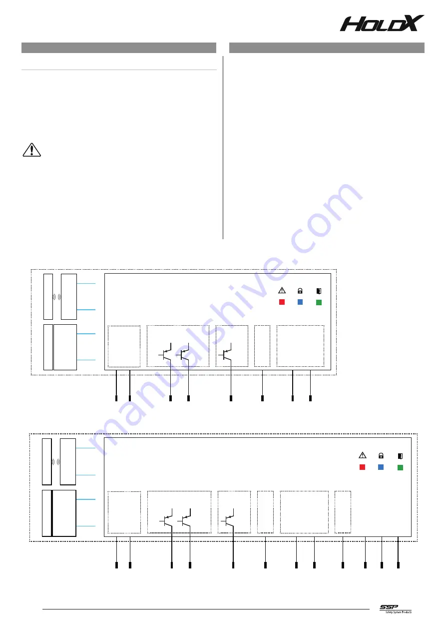
4 .4 Electrical connection diagram
Fig.13:
Safety outputs
power
supply
Saf
et
y sensor
coded
M
ag
net
A
nchor pla
te
Ac
tua
tor
OSSD1 OUT
+24 V
DC
GND
OSSD2 OUT
Diag
nosis OUT
1
3
4
7
Safety inputs
OSSD1 IN
OSSD2 IN
2
6
5
M
ag
net IN
8
HOLDX RS1-P8-...
HOLDX RL1-P8-...
LED diagnosis
Error
Gate
Lock
HOLDX RS1 standalone 8-pin pigtail without reset function
Fig.14:
Safety outputs
power
supply
Saf
et
y sensor
coded
M
ag
net
A
nchor pla
te
Ac
tua
tor
OSSD1 OUT
+24 V
DC
GND
OSSD2 OUT
Diag
nose OUT
1
3
4
7
Safety inputs
OSSD1 IN
OSSD2 IN
2
6
10
11
12
5
M
ag
net IN
8
Reset
9
HOLDX RS1-P12-...
HOLDX RL1-P12-...
LED diagnosis
Error
Gate
Lock
HOLDX RS1 standalone 12-pin pigtail with reset function manual reset