


45
The blows imparted by the equipment used to drive shaft
grouted CSG-RR piles cause short pressure shocks in
the grout, even in excess of 1 MPa, which increase its
penetration efficiency into hole around the pile pipe.
Grouting may be either gravity grouting, where the
grout flows freely into the pipe pile, or pump pressurised.
Gravity grouting is used most often. In the case of long
piles (over 15 m), or those extending substantially below
the water table, pressurised grouting is recommended.
The injection rate of gravity pumping equipment may be
insufficient with long piles. Groundwater pressure pushes
water into the pile pipe if grouting pressure is less than
prevailing water pressure.
The pressure used to pressurise the grout depends on the
soil layers to be penetrated and their possible shearing.
The average recommended pressure for pressurising
grout is 0.5 to 2.5 MPa.
The grout may be either injection grout or grouting
mortar. Injection grout is a mixture of water and cement
that may contain a maximum amount of aggregate
(max. grain size <2 mm) equal to the amount of cement
expressed as percentage by weight. Grouting mortar
consists of aggregate (max. grain size normally <2 mm) in
addition to water and cement.
The water-cement ratio of the grout must be suitable
for the ground conditions, in any event lower than 0.55.
The compressive strength of grout at 28 days must be
at least 25 MPa (C20/25). Used grout must not contain
ingredients that predispose to corrosion or aggravate it.
The pile designer gives instructions for the mixing of the
grout, its admixtures, and the tests to be conducted prior
to its use to determine its consistency, separation and
shrinking. Grouting mortar is always mixed according to
the instructions of the designer.
8. SUPERVISION AND QUALITY CONTROL
OF PILING WORK, MEASUREMENTS
8.1 Supervision and monitoring of piling work
Supervision and monitoring of the installation of steel
piles is implemented according to Ch. 2, Sec. 6.1 of
PO-2016. The quality control of steel pile installation
is based on the implementation and quality plan of the
site (PO-2016, Ch. 2, Sec. 5.1). The piling manager is
responsible for quality control and related measures. The
piling manager may be assisted in the monitoring of piling
work by an external supervisor and/or the site’s responsible
foundation engineer who provides expert monitoring
services. The valid rules and regulations of the Finnish
Transport Agency are observed in the supervision and
monitoring of piling in infrastructure projects.
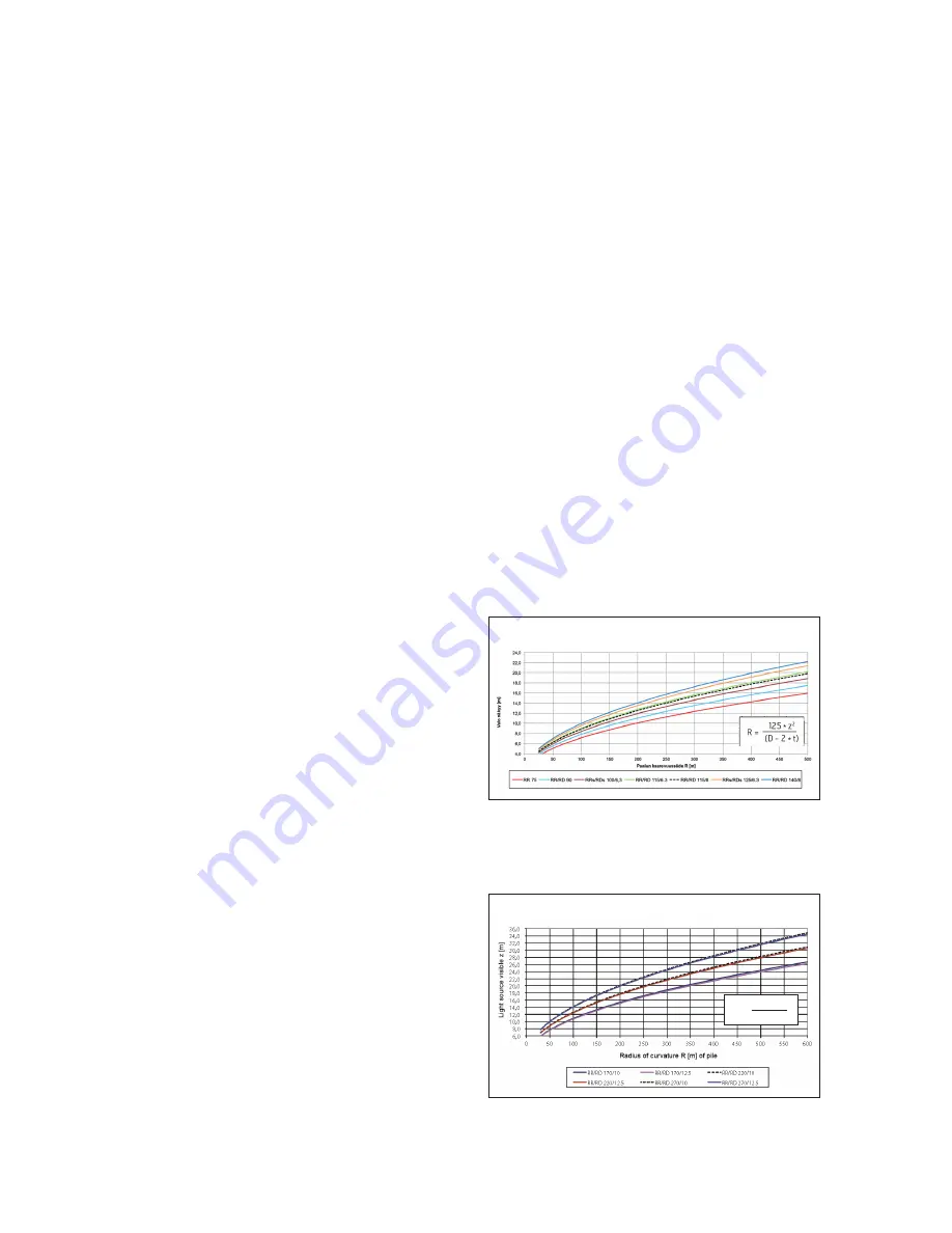
Figure 19. Assessment of curvature of RR/RD170/10 to
RR/RD270/12.5 piles by the torch method.
Figure 18. Assessment of curvature of RR75 to
RR/RD140/10 piles by the torch method.
8.2 Quality control of materials
Quality control of materials is implemented according
to Ch. 2, Sec. 6.1.2 of PO-2016 and their documentation
according to Ch.2, Sec. 7.3 of PO-2001.
8.3 Monitoring measurements during installation
Monitoring measurements during installation are done
according to Ch.2, Sec. 6.2 of PO-2016. Valid guidelines
of the Finnish Transport Agency are observed in
infrastructure projects. Monitoring measurements are
documented as defined in Ch. 2, Sec. 7.3 of PO-2016.
The straightness of RR and RD piles is checked and
documented after their installation. Straightness can
be evaluated by the so-called torch method. It involves
lowering a torch down a pile pipe suspended on a tape
measure and measuring the depth at which the source of
light can no longer be seen. Figures 18 and 19 show radii of
curvature calculated for various piles based on the torch
method. The formula presented in the figures expresses
pile diameter and wall thickness in millimetres.
Curvature of RR/RD170 to RR/RD270 based on torch method
Curvature of RR75 to RR/RD140/10 based on torch method
125 * z
2
(D - 2 * t)
R =