6
B
C
E
D
Desiccant
Dryer
Compressor
Aftercooler
Separator
A
Prefilter(s)
Afterfilter
A
Receiver
Receiver
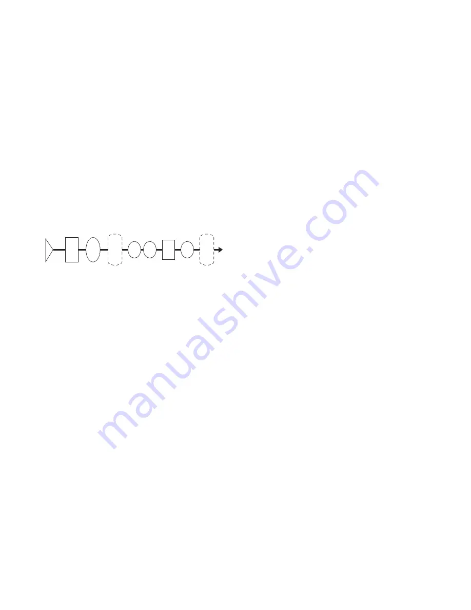
(B & C) PREFILTERS - Adequate filtration is required upstream of the
dryer in order to protect the desiccant bed from contamination. The fol-
lowing filtration is recommended:
B - Particulate/Gross Liquid Removal - On heavily contaminated sys-
tems use a gross contaminant filter to remove solids and high inlet liquid
concentrations.
C - Oil Aerosol Removal - On systems with lubri cated compressors,
use an oil removal filter to remove oil aerosols and protect desiccant bed
from oil contamination.
(D) DESICCANT DRYER
(E) AFTERFILTER - To ensure downstream air purity (prevent desiccant
dust from traveling downstream) adequate filtration downstream of the
dryer is required. Typically 1 micron filtration is specified although finer
filtration is available.
OR
Oil Vapor Adsorber - Use as an afterfilter to remove oil vapor and its
subsequent taste and odor and to protect down -stream components
from solid particles 0.01 micron and larger.
NOTE: By-pass lines and isolation valves are recommended so that
maintenance work can be performed without shutting off the air supply.
2.2 Physical Location
Dryer must be installed with suitable overhead protection.
2.1 Location in the compressed air system.
NOTE: Air Compressor should be adequately sized to handle air system
demands as well as purge loss. Failure to take this into account could
result in overloading air compressors and/or insufficient air supply
downstream.
NOTE: It is desirable to install dryer where compressed air is at the
lowest possible temperature (downstream of aftercoolers) and the high-
est possible pressure (upstream of pressure reducing valves) without
exceeding the maximum working pressure.
(Refer to Figure 2A)
(A) AFTERCOOLER/SEPARATOR - Compressed air entering dryer must
be cooled to at least 120°F (49°C). Use aftercooler and separator if
higher temperatures are present.
NOTE: Installation of a refrigerated dryer ahead of a pressure-swing
desiccant dryer does not increase desiccant dryer capacity or reduce
purge flow requirements. However a cooling unit installed ahead of the
desiccant dryer reduces the inlet air temperature and outlet air dew point.
2.0 INSTALLATION
2.3 Minimum & Maximum Operating Conditions
The compressed air supply inlet should be checked periodically to ensure
that equipment design specifications are not exceeded. Normally the
compressor installation includes intercoolers, aftercoolers, separators,
receivers, or similar equipment which adequately pretreat the com-
pressed air supply in order to avoid excessively high air temperatures
and liquid slugging of downstream equipment.
2.3.1 Compressed air conditions
2.3.1.1 Maximum working pressure: Refer to Serial Number Tag.
WARNING
Do not operate the dryer at pressures above the maximum pressure
shown on the tag.
2.3.1.2 Minimum working pressures: 100 psig (7 barg)
2.3.1.3 Maximum inlet compressed air temperature:
120°F (49°C)
NOTE: If inlet air is higher than 120°F (49°C) the air must be pre-
cooled with an aftercooler.
2.3.2 Ambient temperatures:
Minimum:
Standard units: 35°F (1.7°C)
Units with optional low ambient package: - 10°F (-23°C)
Maximum: 120°F (49°C)
NOTE: If dryer is installed in ambients below 35°F (1.7°C) heat tracing
of the prefilters and inlet piping and valves is necessary to prevent con-
densate from freezing. If installing heat tracing, observe electrical class
code requirements for type of duty specified.
2.4 Mounting
Install dryer on a level pad on floor. Holes are provided in
the floor stand base angles for floor anchors if desired.
NOTE: Floor anchors must be used if area is subject to vibrations.
2.5 Piping
2.5.1 Inlet and Outlet connections
Observe location of inlet and outlet connections as indicated in Figure
2C or 2D and connect inlet and outlet piping.
NOTE: All piping must be supported so as not to bear on the dryers or
filters.
2.5.2 Isolation valves
If isolation valves are installed, it is recommended that gate valves be
used to ensure that dryer is pressurized slowly. This is particularly true
if isolation valves are placed before and after pre- and afterfilters where
rapid pressurization could cause excessive pressure drop across filter
elements.
FIGURE 2A


