background image


19 

CYCLE SPEED


The maximum frequency parameter (f

max

 ) determines the maximum speed of the nozzle at 50% duty cycle and is 

entered as a number of cycles/minute. This parameter can be found in the datasheet of the electric spray nozzle being 
used. 


The spray control panel will calculate the cycle speed to conform to the following requirements (in this order):


• 

As slow as possible to prevent wear of the spray nozzle.


• 

Correct duty cycle this means ON

-

time / (ON

-

time + OFF

-

time) = duty cycle.


• 

OFF time lower or equal than the maximum on/off time parameter. This prevents striping and very low 
frequencies at low duty cycles.


• 

ON time lower or equal than the maximum on/off time parameter. This prevents striping and very low frequencies 
at high duty cycles.


• 

Frequency of the signal higher than the PWM minimum cycles/min setting. This can be used to keep the frequency 
constant for a large range of duty cycles. 


• 

ON and OFF time higher than or equal to the minimum pulse width of the gun. This ensures that the nozzle is able 
to open and close at the same speed as the signal.


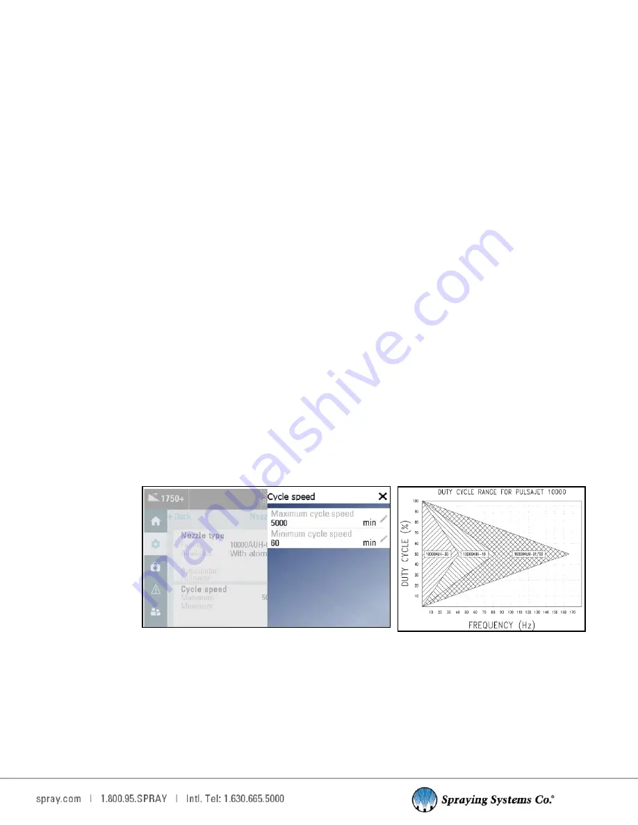
Cycle speed settings allows for the editing of the minimum and maximum cycles per minute, as well as the spray 
thickness. Maximum cycles speed is 7,500 cycles/min, minimum range is 0

-

60 cycles/min.


• 

Maximum cycle speed: 

Maximum speed that the nozzle should switch at for this application. This entry will be 

limited by the type of nozzle selected.


• 

Minimum cycle speed: 

Minimum cycle speed for the 1750+ is recommended for this application. 


Note: 

If you want a constant cycle speed, enter a large spray thickness, and use the minimum cycle speed as your 

required cycle speed entry. The 1750+ will then cycle at this speed whenever possible.


Cycle Speed Example: 


For a nozzle that can achieve 10,000 cycles/min, the minimum pulse width is 3ms. This ensures that the combination 
of duty cycle and cycle speed falls within the triangle curve of the PulsaJet® electric spray nozzles (See figure below). 
The triangle is the approximate operating range of the nozzle. As long as operating parameters (duty cycle and 
frequency) are inside this triangle, the nozzle will operate normally. If the operating parameters are outside the 
triangle, the nozzle will not operate.


Example:


Spray Nozzle: AAB10000AUH

-

03


• 

Maximum cycle speed: 10000 cycles/min


• 

Minimum cycle speed: 0 cycles/min (= disabled)


• 

Minimum pulse width: 3ms


Objective:


• 

Maximum on/off time: 0.010 s or 10ms


• 

Duty cycle: 30%


Editing Cycle Speed Settings


Содержание AUTOJET 1750+

Страница 1: ...AutoJet 1750 Spray Control Panel OWNER S MANUAL ML001750PLUS spray com...

Страница 2: ...ay Timing Modes 21 7 4 Fixed Spray Time 22 7 5 Variable Spray Time 24 7 6 Duty Cycle 27 7 7 Trigger 28 7 8 Tank Level Level Sensor 29 8 Faults and Alarms 30 8 1 Faults and Alarms Settings 30 9 Mainten...

Страница 3: ...y ATTENTION Supplementary information for the user that draws attention to possible problems 2 1 GENERAL SAFETY INFORMATION READ AND FOLLOW INSTRUCTIONS All safety related and operating instructions s...

Страница 4: ...ety precautions when using a pressurized spray system When dealing with pressure applications the system pressure should never exceed the lowest rated component Always know your system all component c...

Страница 5: ...spray period start delay and stop delay times The controller is designed to run both electric and air actuated spray nozzles Can drive Spraying Systems Co electric actuated spray nozzles 3 6 amps max...

Страница 6: ...w delivered to the target surface This provides better flow control with larger spray tips that are less prone to clogging The droplet size is affected by the pressure of the liquid With PSC the dropl...

Страница 7: ...ger interlock or level switch input Trigger Interlock controls the state of run standby mode PLUG AND SPRAY COMPATIBILITY The 1750 can be mounted to the universal frame with mobile cart Plug and Spray...

Страница 8: ...NC Viewer 2 Power on the 1750 if system is not already on 3 In Wi Fi settings on your mobile device locate the Wi Fi SSID typically SSCO_xxxxxx Select connect and enter the default password of SSCO175...

Страница 9: ...a recipe is selected If you have purchased the optional software upgrade and the desired PWM setpoint is set in the recipe between 1 and 100 depending on your application 3 7 ACTIVATING RECIPES A rec...

Страница 10: ...een in Trigger settings Depending on your settings you will have Fixed spray mode Momentary button single shot mode starts a spray when clicked Variable spray mode Toggle button starts stops a spray w...

Страница 11: ...s change the language where applicable view system information and view the activity log LANGUAGE Here you will be able to change the language of the user interface text if available ABOUT SCREEN This...

Страница 12: ...iew these activity reports on the 1750 or export the activity report via a USB stick Note When the system is started for the very first time and for every reboot thereafter it boots up to default user...

Страница 13: ...remain logged in without any activity Setting the value to 0 will leave the user logged in until they choose to log out or the system is rebooted Add new user settings Change Password Allows you to c...

Страница 14: ...p Admin There is a fourth factory settings user SSCO that is included with the system in User Group admin This user is included as a backup option to reset User Group cust_admin passwords if they are...

Страница 15: ...erclockwise to decrease the pressure When the proper air pressure is reached press down on the knob on the regulator to lock it in place Note Your system is equipped with cylinder air for air actuated...

Страница 16: ...o configure most settings if the recipe feature is included in your system configuration 7 1 SPRAY NOZZLE SETTINGS The Nozzle Settings page allows for the editing of the Nozzle type and Cycle Speed No...

Страница 17: ...stem will start spraying when it receives a trigger signal and stop when the trigger signal is removed If your system is equipped with an air atomizing nozzle the 1750 will switch the air output on be...

Страница 18: ...e closing of the electric spray nozzle duration is dependent on nozzle model and supply volt age Gun Nozzle Offset Offset time in milliseconds The difference in the opening and closing time of the Pul...

Страница 19: ...um and maximum cycles per minute as well as the spray thickness Maximum cycles speed is 7 500 cycles min minimum range is 0 60 cycles min Maximum cycle speed Maximum speed that the nozzle should switc...

Страница 20: ...settings sections contains four tabs The drop down list near the top of the page allows you to select which recipe you would like to view edit or apply as the current spray parameters The 1750 is capa...

Страница 21: ...gnal goes low All delay values can be set from 0 00 to 320 00 sec spray times can be set to 0 01 to 320 00 sec SPRAY PERIOD The spray period is the time the object remains under the spray nozzle or th...

Страница 22: ...pray pattern if the start delay is too short In this case the start delay will be extended as required to provide a correct anticipator time This is particularly useful when the start delay may not be...

Страница 23: ...er than the spray time then there is an overlap of two successive spray pulses FIXED SPRAY TIME WITH REPEAT SPRAY This timing mode is used to create a continuous repetition of spray period for a fixed...

Страница 24: ...he object sensor and the spray nozzle Variable spray period INCREASE SPRAY PERIOD Decrease Start delay The spray is started before the object has reached the spray nozzle Increase Stop delay The spray...

Страница 25: ...elay times OVERLAPPING SPRAY EVENTS If spray events overlap the overlapping event will be ignored and the system will continue to spray to ensure the objects are sprayed correctly This situation may o...

Страница 26: ...RAY PERIOD This timing mode is used to create a delayed spray pulse of an unknown period when receiving a trigger signal The start and stop delays are typically the distance between the object sensor...

Страница 27: ...to control Set the value at 20mA to be 100 or another value depending on your trigger source Sensor Offset The minimum level of the sensor offset can control usually starting from 0mA or 4mA Set the s...

Страница 28: ...ill place a trigger button on the home screen that must be pressed every time the system needs to be triggered DI2 Trigger is activated via the Trigger Connection DI2 DI4 DI4 is the trigger interlock...

Страница 29: ...turned on and level is low this will toggle on Invert signal If you have a normally open level switch open until liquid level goes low do not turn this on if you are using a normally closed float tog...

Страница 30: ...ion on the alarm history screen Once the fault has been corrected complete a power cycle of the 1750 to reset and clear the fault Pressing the orange reset button in the top right hand corner of the s...

Страница 31: ...list and your Spray Specialist s Tech contact information SCHEDULER TAB The Scheduler tab will show all upcoming PMs Preventative Maintenance PMs will show the date of next occurrence and are able to...

Страница 32: ...ray Specialist can be found by selecting the Spray Specialist tab These editable boxes contain the name phone number and email address of your Spray Specialist TROUBLESHOOTING The 1750 provides troubl...

Страница 33: ...s Internal temperature too high The temperature in the module is too high Provide sufficient cooling in the cabinet where the module is located 1s High Voltage The voltage on the Vin input is higher t...

Страница 34: ...Check the panel for any loose wires Locate the fuse holder to the right of the power supply and lift the tab on the top of the fuse holder exposing the fuse Due to the type of fuse used a qualified el...

Страница 35: ...ated If this does not occur then ensure that the trigger device is properly wired If problem still occurs then consult the manufacturer s manual for the trigger device For electrically actuated spray...

Страница 36: ...r M12 3 pin male ELECTRICAL JUNCTION BLOCK If multiple PulsaJet or AA250 electric spray nozzles are used the system comes complete with a junction block to con nect the spray nozzles to the unit The j...

Страница 37: ...ffering it should work in most cases SPECIFICATIONS Kit number 040TS04000014W0 Photoelectric sensor Infrared direct reflection sensor with cable connector and bracket NPN NO NC 35 inch 900 mm sensing...

Страница 38: ...present to spray This input always goes to 0V pin 3 To activate this feature on the HMI go to settings trigger and pick trigger source DI2 DI4 For the level switch option DI1 this feature allows you...

Страница 39: ...cables and the splitter The thru beam has a sensor and a receiver Each gets a cable connecting it to the splitter Then the splitter has a cable to connect it to the system The receiver goes to port 1...

Страница 40: ...o signal your system when a fault has occurred in the operation of the spray control panel for example a level sensor going low or a short in one of the nozzle cables To use this fea ture you need to...

Страница 41: ...le trunk male M12 1m whip 2 branches x M12 female coupling nuts TPU parallel wiring Part number LE00M12WYE1M Cable Main M12 M x Flying Leads 16 4 ft 5 m cord length bare leads M12 4 pin M 4 wire Part...

Страница 42: ...drop we recommend keeping the cable length to a reasonable length Never attempt to chain more than four 4 cables together Electric spray nozzle speed and performance will suffer Part number LEXXSD4FD...

Страница 43: ...he black and blue wires dry contacts polarity not important carefully cut back and tape the brown and white wires Run the cable back to the spray control panel and plug into the port labeled T Int Act...

Страница 44: ...ngth Mini DIN M12 3 pin male LE00M12MMDIN3MU PulsaJet Nozzle Cable Main 3m cord length M8 3 pin female M12 3 pin male LEXXSD3M83F030P Trigger Cable Trig 5 m cord length flying leads M12 4 pin female L...

Страница 45: ...ability function or design Other company and product names may be trademarks of their respective companies Warranty is one 1 year on non wear parts from ship date Wear items are covered for manufactur...

Отзывы: