24
Figure 5.5
-
2: Air pressure switch, dial
ATTENTION: The operating pressure of the pumps is 0.1 MPa (14.5 psi) –
0.6
MPa (87 psi). An air
pressure setting outside of the pump operating pressures may cause flow problems or pump
failures.
When the desired pressure setting is reached, push the adjustment knob towards the air pressure gauge until it clicks.
This will lock the adjustment knob in position.
SETTING THE AIR PRESSURE SWITCH
The air pressure switch is used to detect when the air pressure supplied to the system has dropped below the
necessary operating pressure to cycle the piston pumps. This signal will relay a low air pressure fault to the spray
control panel.
HOW TO SET THE AIR PRESSURE SWITCH
1.
The gauge cover must be removed by twisting it counterclockwise until it stops (approx. ¼ inch).
2.
Gently pull the cover away from the gauge. Note the catch in the gauge that align with the slot on the gauge
cover—this is important when reinstalling the gauge cover.
3.
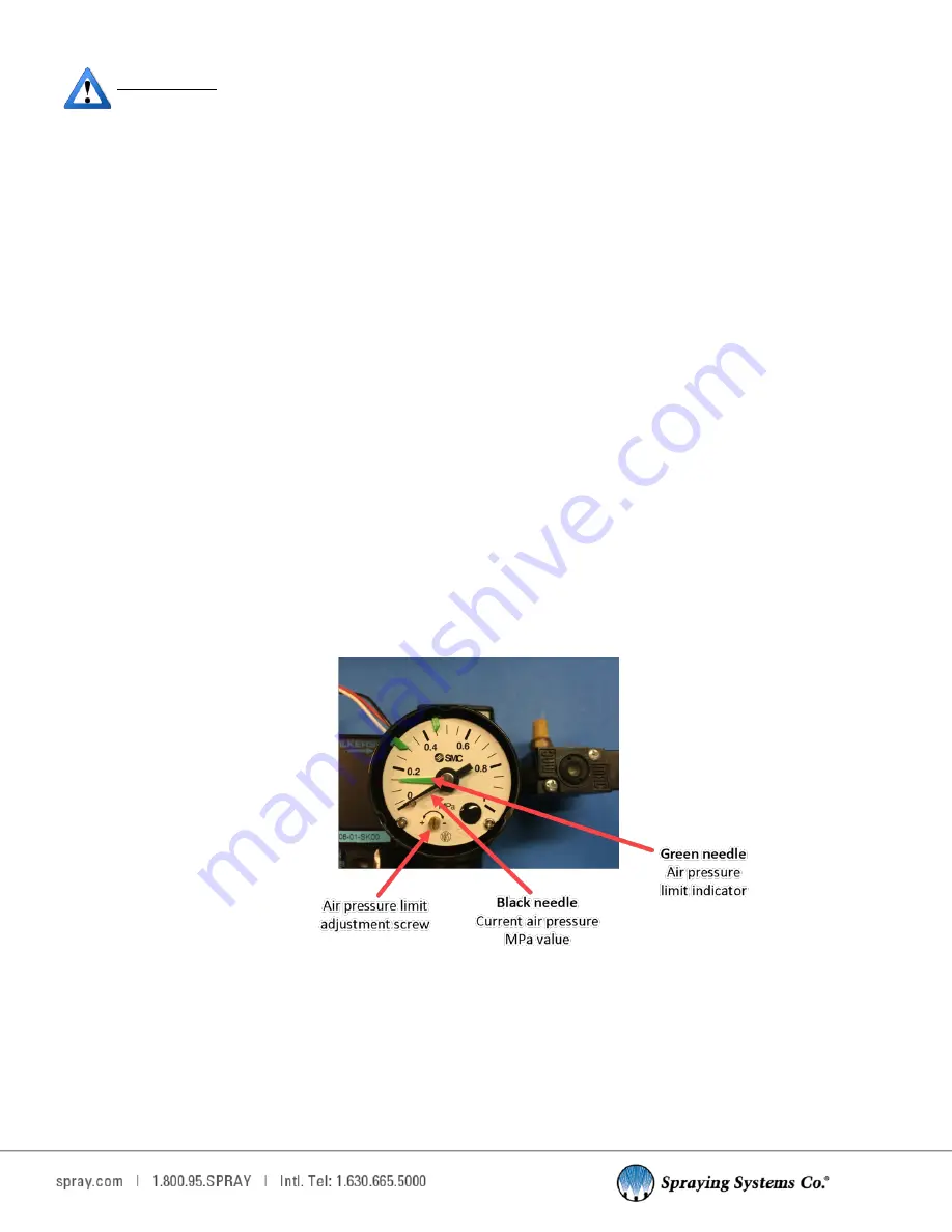
Using a small flathead screwdriver (2.9 mm blade width) adjust the air pressure switch adjustment screw
located on the bottom of the gauge until the green indicator pointer is set to 0.3 MPa. (approx. 40 PSI). This is
the low air pressure set point.
4.
If the compressed air drops below this setting, the switch will alarm the control panel indicating that there is
inadequate air pressure to operate the piston pumps. The red LED Stop button on the control panel door will
flash 10 times indicating there is low air pressure. The green tabs on the gauge can be used to mark the chosen
pressure setting and the chosen low air pressure setting. They have no effect on the actual air pressure setting
or air pressure limit switch settings.
5.
Once the low air pressure setting is complete, replace the gauge cover by lining up the slot (notch in the cover)
to the catch on the gauge housing.
6.
Gently push the cover into the gauge and rotate it clockwise until it stops.


