background image

DLS 400E3 Operating Manual

Spirent Communications - Page


4-5

7104000537  03/04 -2

4.4

Data Formats

This section applies to both the IEEE 488 and RS-232 interfaces.

The host systemhost system adheres to the IEEE 488.2 principle of Forgiving, Listening and Precise Talk-
ing.

The data formats supported by the host system are:

Talking:

a) <NR1> Numeric Response Data - Integer

b) Arbitrary ASCII Response Data

<NR1> is an implicit point representation of an integer (i.e. fixed format). 

Arbitrary ASCII Response Data is a generic character string without any delimiting characters. It is usually
used to send data in response to a query, such as with the *IDN? command.

Listening:

<NRf> Decimal Numeric Program Data

<NRf> is the Flexible Numeric Representation defined in the IEEE.2 standard which can represent just
about any number.

The host system can accept data in the <NRf> format, which means that numbers can be made of a combina-
tion of digits, signs, decimal points, exponents, multipliers, units and spaces. For example, any of the fol-
lowing is a valid representation for -85.0 dBm: -85dbm, -85.0 dbm, -85, -85.0, -8.5e2. If a unit (i.e. dB, pps,
mv, etc) is appended to a number, that unit must be valid and not abbreviated. Note that the period separates
the decimal part of a number.

4.5

Command Syntax

The host system adheres to the IEEE 488.2 format for command syntax. As with the Data Format, the prin-
ciple is Forgiving Listening and Precise Talking.

Commands may take one of two forms, either a Common Command or a Device Dependent Command. The
format of each is detailed in their respective sections Chapter 4 "COMMON COMMAND SET FOR
REMOTE CONTROL", and Chapter 6 "DEVICE SPECIFIC COMMANDS FOR REMOTE CONTROL").
Each type may be preceded by one or more spaces, and each must have one or more spaces between its mne-
monic and the data associated with it.

Common commands are preceded by the character "*". Device Dependent commands are preceded by a
colon, with a colon separating each level of the command. Commands may be either in upper or lower case.
Multiple commands may be concatenated by separating each command by semi-colons. 

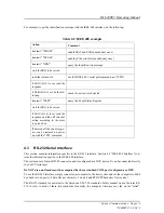
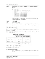
The following are some examples:

Table 2-3:RS-232 Example

Action

Comment

transmit "*ESE 60

enable all the error bits (needed only once)

transmit "*IDN?

query the identification message

read the answer

the messages are always terminated with LF

transmit "*ESR?

check if an error occurred

read the answer

Содержание DLS 400E3

Страница 1: ...Operating Manual DLS 400E3 ADSL European Wireline Simulator Revision 2 March 2004...

Страница 2: ......

Страница 3: ...e IEEE 488 Port GPIB 2 5 2 5 7 2 Connecting the Computer via the Serial Port RS 232 2 6 3 DLS 400E3 CONTROL SOFTWARE 3 1 3 1 About the Software 3 1 3 1 1 Computer Hardware and Software Requirements 3...

Страница 4: ...Example using the RS 232 Interface 6 6 6 3 Wireline Simulator Bypass 6 6 6 4 Setting the Relay Refresh and Micro Interrupt Features 6 7 6 4 1 Synchronization of Commands 6 7 6 4 2 Sub routines for Com...

Страница 5: ...a simple upgrade to an existing DLS 400E2 the DLS 400E3 offers the highest accu racy for testing European ADSL ADSL2 devices The complete DLS E3PKG solution from Spirent Communications combines the DL...

Страница 6: ...se If you already use a DLS 400E2 Wireline Simulator there are upgrades available for DLS 400E3 Please contact your local Spirent Communications sales representative for pricing See Chapter 8 CUSTOMER...

Страница 7: ...tool is recommended for use on a regular basis prior to any extensive tests that must be performed Real world noise has a dramatic impact on the performance of ADSL modems and DSLAMs ETSI TS 101 388 h...

Страница 8: ...simulator The remainder of this manual provides information about the various aspects of the wireline sim ulator such as loop configurations remote control warranty specifications and contact informa...

Страница 9: ...5200E3 Noise Generation System Operating Manual DLS 1200 Library for Spirent Connect SmartBits 200 2000 Installation Guide For new customers please contact Spirent Communications Customer Service abo...

Страница 10: ...DLS 400E3 Operating Manual Page 1 6 Spirent Communications 7104000537 03 04 2...

Страница 11: ...d to both chassis of the DLS 400E3 and switch the power on 2 Ensure that both of the DLS 400E3 chassis have different IEEE addresses 3 Connect a cable from the computer to chassis 1 If using IEEE 488...

Страница 12: ...or even switched off The ATU R and ATU C and their wiring should be physically separated as crosstalk can occur between cabling Configure the cables so that they are not touching and the cable connect...

Страница 13: ...B of unit 1connects to side A of unit 2 This one foot RJ 45 cable is provided as an acces sory within the DLS 400E3 package See Section 2 4 4 for RJ 45 connector details 2 4 3 Connecting to Analog De...

Страница 14: ...al Note RJ 11 male connectors can also mate to RJ 45 female receptacles These connections are balanced WARNING The maximum input to the DLS 400E3 must not exceed 30 dBm between 50 Hz and 1 kHz Exceedi...

Страница 15: ...ased which can inject noise differentially onto the wireline with a 4 KOhm Thevenin output impedance The DLS 400E3 also has 2 50 Ohm BNC external noise inputs located on the rear panel These inputs ar...

Страница 16: ...S 400E3 can use any valid IEEE 488 address from 0 to 30 You can change the address by using the DIP switch on the back of the unit The weighting is as follows The following figure shows the default sw...

Страница 17: ...tware Requirements You require the following to configure and control a simulator through either the serial port or IEEE 488 interface If using the DLS 400E3 Software provided with the unit a computer...

Страница 18: ...le click the icon on your desktop The DLS 400E3 DLS 400E3 Available Configurations window appears Figure 3 1 DLS 400E3 Software Main Window 3 4 Accessing the Control Window s The DLS 400E3 control win...

Страница 19: ...ted products connected via RS 232 or the IEEE 488 communication buses optional interface The program automatically displays the connected units in the display area OR 2 Click User Defined then manuall...

Страница 20: ...ating Manual Page 3 4 Spirent Communications 7104000537 03 04 2 Figure 3 3 DLS 400E3 Unit 1 Control Window To access the DLS 400E3 chassis 2 controls click the Unit 2 Tab Figure 3 4 DLS 400E3 Unit 2 C...

Страница 21: ...e simulator you wish to configure from the drop down list Your choices are 1 30 The default IEEE 488 address is 14 Factory address settings for unit 1 and unit 2 are 14 and 15 respectively OR ComPort...

Страница 22: ...or the modems Relay Refresh Check this check box to enable the relay refresh and inject whetting current on the simulated loop Clear this check box to disable the relay refresh feature 3 5 4 Compensat...

Страница 23: ...ensate the standard slot settings for the selected test loop 3 5 5 Selecting the Test Loop Note In the Loop Selection area the field names change based on the value you select in the Standard field Fo...

Страница 24: ...or each unit Gauge Displays the gauge of wireline for each of the 24 wireline card slots for each unit Tap Check this check box to set the card in the associated slot to represent a bridged tap Clear...

Страница 25: ...following graph from the ITU T G shdsl standard illustrates the specified micro interruption Figure 3 5 Micro Interruption Test Circuit The standard specifies two configurations based on the powering...

Страница 26: ...ld or use the up and down arrows on the spin box The range is 3 to 360 seconds Test Interval TI Enter the test interval duration in seconds directly in the field or use the up and down arrows on the s...

Страница 27: ...ed data Both interfaces use the same command set and pro duce the same results Section 4 2 IEEE 488 Interface and Section 4 3 RS 232 Serial Interface describe features specific to one particular inter...

Страница 28: ...signal or both Messages from the system are always terminated with a Line Feed character and the IEEE 488 1 EOI signal Note that some software languages may automatically append a carriage return and...

Страница 29: ...haracter 1 stop bit and RTS CTS hardware flow control The RS 232 standard is equivalent to the European V 24 V 28 standards In this manual we use the term RS 232 to refer to both of these two standard...

Страница 30: ...he line feed character decimal 10 hex 0A LF To ensure that no characters are left in the receive buffer of the system from a pre vious incomplete command you can send the line feed character by itself...

Страница 31: ...a unit i e dB pps mv etc is appended to a number that unit must be valid and not abbreviated Note that the period separates the decimal part of a number 4 5 Command Syntax The host system adheres to t...

Страница 32: ...begin with a colon the simulator assumes that the command is at the same level as the previous command For example to set the impulse it is NOT necessary to specify sourceB IMPULSE for each parameter...

Страница 33: ...unction Sets the Event Status Enable Register ESER using an integer value from 0 to 255 repre senting a sum of the bits in the following bit map Bits 7 to 0 have values of 128 64 32 16 8 4 2 and 1 res...

Страница 34: ...roceed as normal after this command but be prepared to receive the 1 at any time PSC NRf Power on Status Clear Type Status and event command Function Indicates if the unit should clear the Service Req...

Страница 35: ...Service Request Enable Query Type Status command Function An integer value representing the value of the Service Request Enable Register is placed in the output queue The possible values are listed in...

Страница 36: ...ion with the host system is frozen until all pending operations are completed 4 8 Status Reporting There are two registers that record and report the system status the Status Byte Register STB and the...

Страница 37: ...current operation is complete bit 1 Request Control The host system does not have the ability to control the IEEE bus and so this bit is always 0 bit 2 Query Error There was an attempt to read an empt...

Страница 38: ...st system can determine when the operation is completed by waiting for SRQ or by reading the status byte with the serial poll or with STB if corre sponding bits are enabled If the program uses the OPC...

Страница 39: ...csv files 1 Standards File associates an ID to every possible loop configuration supported by the DLS 400E3 2a DLS 400E3 Standard Slot Settings File associates each ID to generic simulator compensati...

Страница 40: ...files associate this ID to exact length settings for each or the 24 slots in unit 1 and unit 2 See the example for ID 19 as shown in Figure 5 2 Figure 5 2 E3 Standard Slot Settings File These setting...

Страница 41: ...E3 may be terminated with either a Line Feed character ASCII LF decimal 10 hex 0A an IEEE 488 EOI signal or both RS 232 messages must be terminated with a line feed character Messages from the DLS 400...

Страница 42: ...esolution of the parameter The DLS 400E3 system is a slot based configuration and therefore device dependant commands should fol low the structure listed below For automating scripts you can open the...

Страница 43: ...18 500 M INLINE SET SLOT 23 500 M INLINE The listed slot settings below are default values and can be varied between inline and tap However Unit 2 Slot 1 can only be set as a bridged tap and cannot be...

Страница 44: ...s previous settings You may want to create a loop based command which sets all slots to 0 length prior to setting a new loop Unit 2 SETTINGS SET CHANNEL BYPASS NO SETTING CHANNEL DIRECTION FORWARD SE...

Страница 45: ...s allowing a minimum of 15 meter increments A Bypass Card type is returned for any other slot not occupied by a wireline The type Empty Slot is returned if no card wireline or bypass is installed in a...

Страница 46: ...n To set a specific slot do the following 1 transmit SET SLOT 1 50 METERS INLINE 2 check that the REMOTE LED is green To send and receive messages with error checking follow these steps 1 set all rele...

Страница 47: ...pecified test via SCPI command the following proce dure has to be followed The user should establish the desire Test Interval TI and Signal Period T Then divide TI by T to obtain the number of require...

Страница 48: ...ot 1 100 tap Step 2 OPC Step 3 wait SRQ raised or wait for some time Step 4 ESR Step 5 check till the bit 0 of ESR is set Step 6 setting channel interrupt side A 3 Using OPC OPC is Operation Complete...

Страница 49: ...ion pin 1 and 2 which resets only the interface when IFC is received The only tool required to change the shunt s position is a screwdriver Ensure that the cover card retainer and card stabilizer hard...

Страница 50: ...ption 6 Re install the controller and ensure a tight fit with the connectors on the motherboard 7 At this time plug the unit in and turn it on Run the software that came with the unit and ensure the p...

Страница 51: ...rive Suite P S La Mesa CA 91942 Phone 619 697 8790 Fax 619 697 5955 ITU T ADSL2 European Asymmetric Digital Subscriber Line ADSL Transceivers International Telecommunication Union Place des Nations CH...

Страница 52: ...DLS 400E3 Operating Manual Page 7 2 Spirent Communications 7104000537 03 04 2...

Страница 53: ...gin htm 8 2 Protecting Your Investment Spirent Communications is committed to providing the highest quality products and customer support possi ble An annual calibration is required to ensure that you...

Страница 54: ...tandards and Technol ogy N I S T traceable calibration that expires one year from the original ship date With ISO 9000 and other manufacturer specific metrology requirements timely calibrations become...

Страница 55: ...e not covered under this warranty the regular repair charges shall apply to any repairs made to the equipment For international customers please contact your local Spirent Communications sales represe...

Страница 56: ...DLS 400E3 Operating Manual Page 9 2 Spirent Communications 7104000537 03 04 2...

Страница 57: ...e of the unit It is highly recommended that all shipments are marked with labels indicating that the contents are fragile If sending a unit back to the factory ensure that the Return Material Authoriz...

Страница 58: ...DLS 400E3 Operating Manual Page 10 2 Spirent Communications 7104000537 03 04 2...

Страница 59: ...op 7 MAE 1 0 dB over band used by DUT to a maximum of 90dB in ideal conditions Average Noise Floor 150dBm Hz within the ADSL Band Construction Main chassis plus plug in controller wireline modules and...

Страница 60: ...consumption 120 VA max Line Fuses Type T 2A 250V SLOW BLOW 2 required 5 mm x 20 mm Environmental Operating Temperature 10 C to 40 C 50 F to 104 F Storage Temperature 10 C to 40 C 50 F to 104 F Humidi...

Страница 61: ...apter 11 SPECIFICATIONS of this manual WARNING To avoid electrical shock do not operate the equipment if it shows any sign of damage to any portion of its exterior surface such as the outer casting or...

Страница 62: ...ny devices or cords connected to it are properly grounded 12 2 2 Operating the Unit Do not operate the equipment when its covers or panels have been removed Do not operate equipment if an interruption...

Страница 63: ...ications Page 12 3 7104000537 03 04 2 12 3 Symbols When any of these symbols appear on the unit this is their meaning EQUIPOTENTIALITY FUNCTIONAL EARTH TERMINAL PROTECTIVE GROUNDING CONDUCTOR TERMINAL...

Страница 64: ...DLS 400E3 Operating Manual Page 12 4 Spirent Communications 7104000537 03 04 2...

Отзывы: