


DLS 400E3 Operating Manual
Spirent Communications - Page
2-1
7104000537 03/04 -2
2.
GETTING STARTED
2.1
Receiving and Unpacking the Unit
Each DLS 400E3 chassis has been shipped in a reinforced shipping container. Please retain this container in
case you need to ship the wireline simulator to another location or for repair. The DLS 400E3 system con-
tains the following:
•
DLS 400E3 1/2 and DLS 400E3 2/2 chassis
•
1 power cord per chassis
•
2 extra fuses per chassis
•
1 RJ-45 chassis blue unsheilded twisted pair (UTP) connection cable
•
1 RS–232C interconnnection cable per chassis
•
1 IEEE 488 interconnection cable per chassis
•
2 CF–to–twin RJ–45 adaptors per chassis
•
DLS 400E3 Control Software
•
DLS 1310 E3 Compensation Software
•
DLS 400E3 ADSL (European) Wireline Simulator Operating Manual
Check that you have received all the items on the list and report any discrepancies to Spirent Communica-
tions. See Chapter 10 "SHIPPING THE UNIT" for information.
2.2
Setup Overview
To test:
1) Connect the power cord to both chassis of the DLS 400E3 and switch the power on.
2) Ensure that both of the DLS 400E3 chassis have different IEEE addresses.
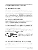
3) Connect a cable from the computer to chassis 1. If using IEEE 488 cable, connect a second IEEE
488 cable from chassis 1 to chassis 2. If using serial cable to both chassis, a serial port is required
on the PC to chassis 1 and chassis 2.
4) Connect your digital subscriber line access multiplexer (DSLAM) equipment to side A of chassis 1.
5) Connect side B of chassis 1 to side A of chassis 2 using the supplied blue UTP cable.
6) Connect your customer premise equipment (CPE) equipment to side B of chassis 2.
7) Start the DLS 400E3 Software.
8) Select the wireline simulator used (i.e. DLS 400E3) by selecting the “User Defined” selection in
the main window. You can also select “Detect Units”, as this allows the DLS 400E3 program to poll
for any connected devices over Serial or IEEE 488 interfaces.
9) Select “Connect to Units”.
10) Select the desired test loops via the drop-down menus.
11) Select the desired impairments if a external DLS 5200E3 noise generator or internal DLS 5A01H
noise card is installed.
12) Begin testing.
See the following sections for detailed information.
Содержание DLS 400E3
Страница 1: ...Operating Manual DLS 400E3 ADSL European Wireline Simulator Revision 2 March 2004...
Страница 2: ......
Страница 10: ...DLS 400E3 Operating Manual Page 1 6 Spirent Communications 7104000537 03 04 2...
Страница 52: ...DLS 400E3 Operating Manual Page 7 2 Spirent Communications 7104000537 03 04 2...
Страница 56: ...DLS 400E3 Operating Manual Page 9 2 Spirent Communications 7104000537 03 04 2...
Страница 58: ...DLS 400E3 Operating Manual Page 10 2 Spirent Communications 7104000537 03 04 2...
Страница 64: ...DLS 400E3 Operating Manual Page 12 4 Spirent Communications 7104000537 03 04 2...


