SpectraLink Corporation
Installation, Configuration, and Administration
NetLink Telephony Gateway
Part Number: 72-0065-02-R.doc
Page 25
7.2
Installing Multiple NetLink Telephony Gateways
If installing more than one NetLink Telephony Gateway, the ESD bonding strap(s)
must be installed between adjacent Gateways.
Mount Gateway
1.
See directions for installing a single Gateway in previous section. Measure
carefully to allow no more than ½” between Gateways. Drill holes and place
screws.
2.
Position each NetLink Telephony Gateway with Connector A to the right
(horizontal) or bottom (vertical). Slide the NetLink Telephony Gateway over the
screws until the unit drops into place in the keyhole opening.
3.
Tighten screws fully.
Install bonding straps
1.
Remove the screws from the bottom (vertical mount) or left (horizontal mount)
of adjacent units.
2.
Place the ESD strap over the pilot holes that span two units and hold it against
the plywood backboard or rack.
3.
Place the star washer on top of the ESD strap.
4.
Insert the #8 x ¾ screw and tighten to leave 1/8 to 1/4 inch gap from the wall.
5.
Repeat for all ESD straps.
When installing a TGA116, the grounding terminal in the rear panel of
each unit must be electrically connected to earth ground. Consult the NEC
manual and local codes for instructions on making the connection to the
ground.
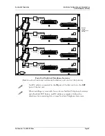
Install IPC cables
To connect IPC cables on four or fewer NetLink Telephony Gateways (without a
NetLink SVP Server):
1.
Mount the NetLink Telephony Gateways.
2.
Connect the IPC cable from the
IPC OUT
Port of the first unit to the
IPC IN
Port
of the adjacent unit.
3.
Repeat step 2 until all units are connected.
The following illustration shows a horizontally mounted system, with NetLink
Telephony Gateway number one at the bottom.

