SpectraLink Corporation
Installation, Configuration, and Administration
NetLink Telephony Gateway
Part Number: 72-0065-02-R.doc
Page 24
7.
Install NetLink Telephony Gateway
7.1
Mount to Rack or Wall
The NetLink Telephony Gateways can be wall mounted either horizontally or
vertically. Gateways may also be rack mounted in a standard 19 inch rack. A Rack
Mount Kit must be purchased separately for a rack mount installation.
To Mount
Gateways…
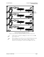
Connector A is…
Mount the Units….
Clearance Between Gateways
Horizontally
To the right side of the
NetLink Telephony
Gateway, with labels in
correct position.
On top of one another
Leave a little more than ¼ inch between
adjacent units, allowing easy removal of
units via the keyhole openings on the rear
panel.
Do not leave more than ½ inch spacing or
the ESD bonding strap will not fit correctly.
To set the desired unit spacing, leave (0.9”
+ desired gap) between adjacent mounting
holes.
Vertically
At the top of the
NetLink Telephony
Gateway
Side by side
Adjacent units should be physically
touching
Mount the NetLink Telephony Gateway to rack
The Rack Mount Kit is designed for mounting equipment in a standard 19-inch rack
and should contain the following equipment:
•
Mounting plates: Two for each Gateway to be mounted.
•
Screws: Four rack mount screws for each Gateway to be mounted.
Follow these steps to mount the Gateway to a rack:
1.
Remove the corner screws from the Gateway.
2.
Screw the U-shaped end (round screw holes) of the two mounting plates to the
Gateway.
3.
Screw the other end of the two mounting plates (oblong screw holes) to the rack.
Connector A should be to the right.
Mount NetLink Telephony Gateway to wall
Follow these steps to mount one NetLink Telephony Gateway to a wall:
1.
Using a 1/8-inch drill bit, drill four pilot holes, on 1.84 by 12.1 inch centers
(approximately equivalent to 1-13/16 inch by 12-1/8 inch).
2.
If installing only one NetLink Telephony Gateway, insert the #8 x 3/4 inch
screws in the pilot holes and tighten, leaving a 1/8 to 1/4 inch gap from the wall.
Position the NetLink Telephony Gateway with Connector A to the right
(horizontal) or bottom (vertical).
3.
Slide the NetLink Telephony Gateway over the screws until the unit drops into
place in the keyhole opening.

