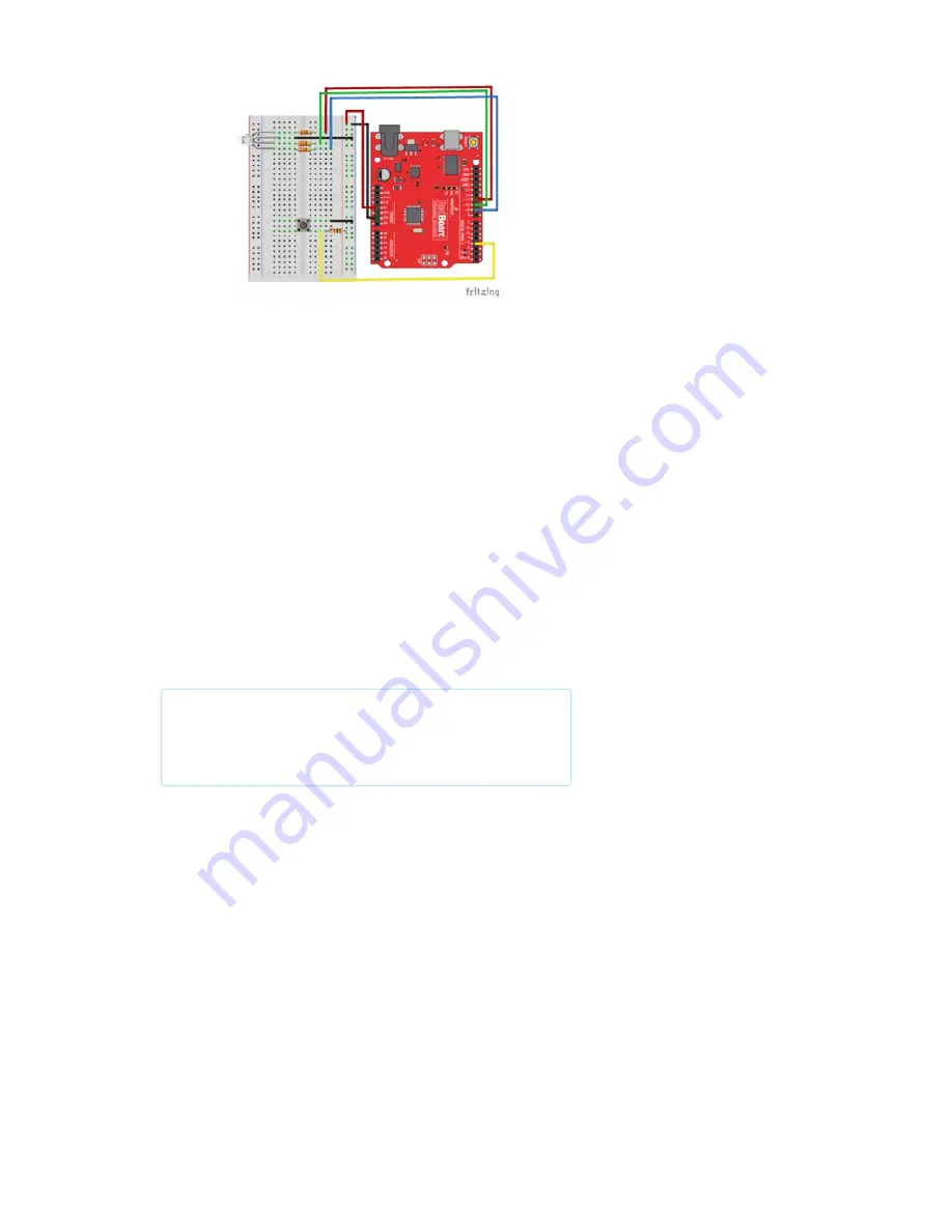
Having a hard time seeing the circuit? Click on the wiring diagram for a
closer look.
Digital Input
Previously we’ve used the analog pins for input; now we’ll use the digital
pins for input as well. Because digital pins only know about HIGH and LOW
signals, they’re perfect for interfacing to pushbuttons and switches that also
only have “on” and “off” states.
We’ll connect one side of the pushbutton to ground, and the other side to a
digital pin. When we press down on the pushbutton, the pin will be
connected to ground, and therefore will be read as “LOW” by the
RedBoard.
But wait – what happens when you’re not pushing the button? In this state,
the pin is disconnected from everything, which we call “floating.” What will
the pin read as, then – HIGH or LOW? It’s hard to say, because there’s no
solid connection to either 5V or ground. The pin could read as either one.
To deal with this issue, we’ll connect a small (10K, or 10,000 Ohm)
resistance between the signal pin and 5V. This “pull-up” resistor will ensure
that when you’re NOT pushing the button, the pin will still have a weak
connection to 5 volts, and therefore read as HIGH.
Advanced:
When you get used to pull-up resistors and know when
they’re required, you can activate internal pull-up resistors on the
ATmega processor in Arduino. See
http://arduino.cc/en/Tutorial/DigitalPins for information.
Open the Sketch
Open the Arduino IDE software on your computer. Coding in the Arduino
language will control your circuit. Open the code for Circuit 5 by accessing
the “Tinker Kit Guide Code” you downloaded and placed into your
“Examples” folder earlier.
To open the code go to:
File > Examples > Tinker Kit Guide Code >
Circuit_05
You can also copy and paste the following code into the Arduino IDE. Hit
upload, and see what happens!
Page 31 of 63


