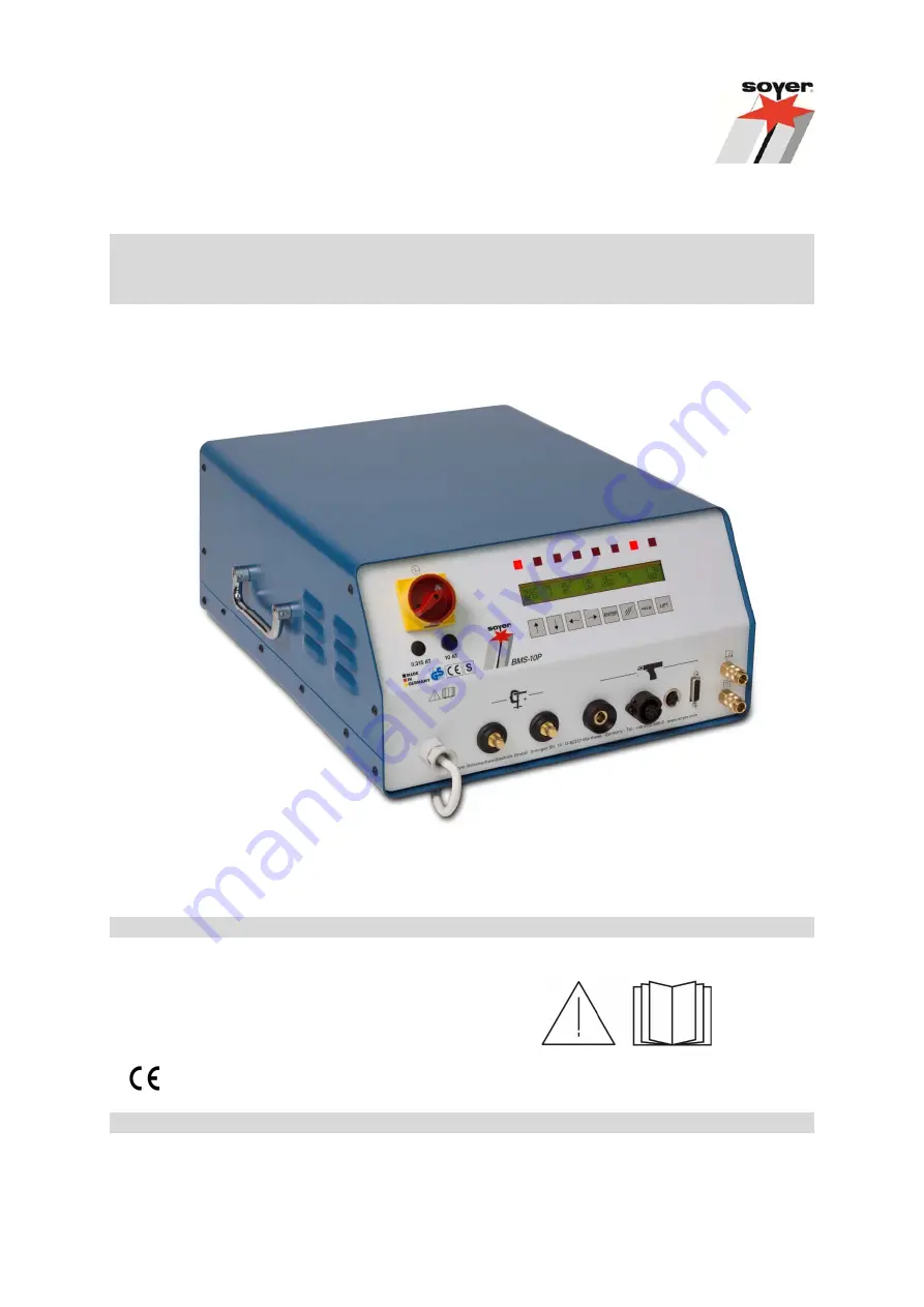
BMS-10P Operating Instructions Stud Welder
GB
: English Version
Read these operating instructions before starting any work!
Doc.ID:
P00297
Date of issue: 06.2013
www.soyer.de
Страница 1: ...BMS 10P Operating Instructions Stud Welder GB English Version Read these operating instructions before starting any work Doc ID P00297 Date of issue 06 2013 www soyer de...
Страница 2: ......
Страница 3: ...support Order No Code designation Note P01063 BMS 10P Mains voltage 230 V OPTION 115 V 1 with capacitance change over 33 000 99 000 F 1 The BMS 10P stud welder is suitable for operation with 115 V or...
Страница 4: ...Heinz Soyer Bolzenschwei technik GmbH It is prohibited to distribute or reprint this document It is also prohibited to exploit or disclose its contents unless permission has been expressly granted Non...
Страница 5: ...s Any unauthorised modification to this machine automatically annuls this declaration Designation of machine Stud welding device Machine type BMS 10P BMS 10PV Machine no ______________________ Applica...
Страница 6: ...ion of stud welder 14 3 1 Description 14 3 2 Capacitor discharge stud welding technology 14 3 3 Technical data 15 3 4 Interfaces BMS 10P 16 4 Installation of the stud welding system 18 5 Start up 19 5...
Страница 7: ...6 3 Special function Setting the language Display of software version number 43 6 6 4 Special function Setting the feeder times 43 6 6 5 Special function Setting the feeder operation 44 6 6 6 Special...
Страница 8: ...s airbags Ensure that the welding equipment is not operated near electronically sensitive life support equipment such as in intensive care units in hospitals Persons with pacemakers may neither operat...
Страница 9: ...ammable materials and liquids such as oil fuel etc must be removed prior to the start of work Electronic equipment e g airbags and the use of explosive substances for fuel supply require further safet...
Страница 10: ...roduct or to an object surrounding it Instructions for application and other useful information facilitating the proper use of the product Safety symbols The following pictographs for warnings prohibi...
Страница 11: ...ons Failure of prescribed methods for maintenance Danger to persons through electrical mechanical thermal and or acoustic influences 1 4 Before starting to weld Check the state of all cables and cable...
Страница 12: ...ms please contact either our parent company or our field engineers 2 3 Marketing and service If you have any questions regarding the operation of the feeder retrofits for special applications or if yo...
Страница 13: ...s occur first try to detect and eliminate the causes according to the list in the Troubleshooting chapter of these operating instructions In all other cases contact our service department If you requi...
Страница 14: ...ns occur The stud welder is equipped with eight keys eight light emitting diodes LED and a two lined text display at the front panel The stud welder is adjusted via the keys The operating state during...
Страница 15: ...50 60 Hz 10 A 2 OPTION 115 V Fuse T 10 A 5 x 20 mm time lag fuse Type of cooling F System of protection IP 21 Dimensions 430 x 220 x 560 mm w x h x d Weight 1 26 kg 1 Colour RAL 5009 azure blue Techn...
Страница 16: ...s the workpiece 4 9 Signal 3 Charge is ready Contact is made after the set charging voltage has been reached 6 5 Reset external Error reset external Contact resets error messages RS 232 interface bidi...
Страница 17: ...responds to the current mains voltage CAUTION The isolated ground receptacle is protected by 3 15 A Never connect any additional appliances such as stud welders Setting the mains voltage for 115 V or...
Страница 18: ...d ensure a safe and stable position for the welding equipment Make sure there is sufficient free space around the air apertures otherwise the device safety mechanism will respond and interrupt the wel...
Страница 19: ...9 Control cable socket 10 Test jack GUN 11 Test jack EARTH 12 Gun cable socket 13 Earth cable connectors 14 Mains cable Rear view 15 CNC interface 16 Feeder interface 17 Interface RS 232 18 Interface...
Страница 20: ...fting magnet of the welding gun 5 1 3 Description of LED displays The respective operating states may be read via the LED displays LED Description 5 1 LED Ready LED lights up when capacitor battery ha...
Страница 21: ...IFT Lift test It allows activating the lifting magnet of the gun head to control the setting without welding operation MEAS The operating mode MEAS allows you to determine the desired values for a wel...
Страница 22: ...for electrical connections as indicated on the type plate of the stud welder Earth cable socket The earth cable socket serves to connect the earth clamps to the stud welder Control cable socket and we...
Страница 23: ...y ALTER PARAMETERS Downward alteration of selected parameters represented blinking in the display Function key SELECT PARAMETERS Selection of parameters to be changed shifting of the blinking symbol t...
Страница 24: ...n When the quality control is switched on the stud welder locks if welds are outside the tolerance It can be reset by pressing the LIFT key or ENTER key please refer to the description of the quality...
Страница 25: ...at short intervals This can cause the thermo safety mechanism protecting the lifting magnet to react and the current supply for the magnet will be interrupted This condition is shown as error message...
Страница 26: ...m to be copied The copied program appears on the display Reference values which have been stored for the quality control will also be copied 5 5 Deleting welding programs It is possible to delete user...
Страница 27: ...able to earth cable connectors and lock by turning to the right until stop Attach earth clamps to workpiece Ensure optimum contact with workpiece If necessary grind the area to be welded contact area...
Страница 28: ...assurance of stud welding joints The welding parameters were determined with the BMS 10P stud welder and the PS 3 stud welding gun using a lift adjustment of about 2 5 mm A steel plate with a thickne...
Страница 29: ...et e g PS 3 SK 5AP Check the setting for the height of lift Position welding gun with weld stud on the workpiece When earth connection is made and the stud in the gun touches the workpiece the LED Stu...
Страница 30: ...to the right The lifting height shall amount to approximately 2 mm This procedure can be repeated as frequently as required To avoid overheating the magnetic coil a waiting time of approx one second...
Страница 31: ...th does not exceed 35 mm When using long weld studs with the small sized PS 0K and PS 1K welding guns however it is necessary to shorten the stud chucks stop screw Insert weld stud into stud chuck The...
Страница 32: ...et wrench Insert the chuck into the spring piston and push it firmly until it comes to a stop Hand tighten sleeve nut by means of SW 17 socket wrench Ensure stud protrusion is set between 1 5 mm and 3...
Страница 33: ...connected to the earth connection of the stud welder the drop time will be shown in milliseconds on the display If the workpiece is not connected to the earth connection No grounding will appear on t...
Страница 34: ...ance sleeve ATTENTION DISCONNECT COMPRESSED AIR Disconnect the air connections located on the front panel of the stud welder prior to replacing the conversion kit Please ensure that the stud welder is...
Страница 35: ...g so Tighten stud feed tube with grub screw 2 Please note Loosen grub screw 2 and press in the locking pin 1 when mounting or dismounting the welding gun Connect compressed air min 5 bar max 7 bar to...
Страница 36: ...e which is connected to the earth connection of the stud welder the drop time will be shown in milliseconds on the display If the workpiece is not connected to the earth connection No grounding will a...
Страница 37: ...he workpiece at a 90 degree angle to the workpiece Check once again the selected parameters Release welding process by pressing the push button During the welding process keep the gun steady After com...
Страница 38: ...un head CNC table robot earth connections etc are prerequisites for the successful application of the quality control The SK 5AP welding head or PS 3A PS 3P welding guns are suitable for the quality c...
Страница 39: ...le deviation of the quality control Value TOL Tolerance O Quality control off 1 smallest tolerance limit 10 maximum tolerance limit Now the measured values of each weld are compared with the determine...
Страница 40: ...lities to collect additional reference values at any time 1 Select again operation mode MEAS this time however using option Store as measured values by pressing Arrow left key This enables carrying ou...
Страница 41: ...ng special functions are available 6 6 1 Special function Deleting RAM This special function serves as RESET function for the stud welder e g for eliminating errors or when initiating the stud welder...
Страница 42: ...n of the automatic stud reload process on off on Lift Extension of lift time Here you can prolong the specified Lift time prior to the welding process 0 2000 ms 0 Res Err Automatic error reset Here yo...
Страница 43: ...Please follow the instructions shown on the display 6 6 4 Special function Setting the feeder times With automatic operation this special function serves to adapt the control to the feeder parameter 1...
Страница 44: ...n blow off position 0 20 000 ms 0 Feeder This parameter serves to adjust the feeder type connected UVRBMS and UVRBMK can be set as feeder types 6 6 5 Special function Setting the feeder operation This...
Страница 45: ...ce can be used Protocol example Translation BMS 10P SOYER STUD WELDER TEST RECORD Item no Date Lot no Prod date Lot size Sampl size Place no Name Statistic evaluation Number of welded studs 456 Number...
Страница 46: ...lear protocol With this function all digits of the protocol function are set to zero i e logging deletes all studs and errors collected so far This function should only be selected after printing out...
Страница 47: ...ngth of the welding joint welding zone will always be stronger than that of the stud or base material The following tests are carried out in general practice Visual inspection Bend test Please also re...
Страница 48: ...s adequately trained personnel suitable service equipment and the means to carry out all necessary works 8 2 Important instructions for all service works DANGER Always disconnect the mains cable from...
Страница 49: ...d SOYER personnel The perfect function of your stud welder can only be guaranteed when original SOYER spare parts are used CAUTION Disconnect the mains cable from the mains supply before replacing any...
Страница 50: ...ady must light up Digital display lights up Welding points and or earth connection points at the workpiece are not blank LED display Stud on Workpiece does not light up Prepare workpiece or studs acco...
Страница 51: ...e surface Stud face deformed Use new welding studs Welding gun in tilted position Position welding gun evenly on the workpiece Welding energy is set too low Readjust welding energy Poor earth connecti...
Страница 52: ...er corresponds to safety class IP 21 Please observe that this system of protection is not suitable for being operated or transported in the rain 11 Terms of warranty We warrant for this equipment for...
Страница 53: ...arc stud welding DVS Information Sheet 0903 Capacitor discharge stud welding with tip ignition DVS Information Sheet 0904 Practical information Arc stud welding EN 14555 Arc welding of metallic mater...
Страница 54: ...www soyer de Heinz Soyer Bolzenschwei technik GmbH Inninger Stra e 14 82237 W rthsee Tel 49 8153 8850 Fax 49 8153 8030 E mail info soyer de www soyer de...