Exterior Lightbar Connect-n-Go System
nROADS Connect-n-Go 1018
10.
FLASH PATTERNS & CONFIGURATIONS
Button 1 – Flash 2
36”
Button 2 – Front Scene
42”
Button 3 – Full Scene
48”
Button 4 – Alley Left
54”
Button 5 – Rear Work
60”
Program 1 - Flash Patterns 1:
1. Press and hold buttons 1 and 2 for 5 seconds.
2. The arrow left and arrow right indicators will flash and system will transition to warning flash mode 1 to indicate system is in this programming mode.
3. Press the arrow left and right buttons to decrement or advance the patterns. The pattern index will be reflected on the buttons in BCD (see table on Page 12.)
The buttons can also be pressed to enter a pattern number directly.
4. Press the FRONT button to exit programming mode, REAR to decrement to the previous program mode, or FULL to advance to next programming mode.
Program 2 - Flash Patterns 2:
1. Press and hold buttons 1 and 3 for 5 seconds.
2. The arrow left and alley left indicators will flash and system will transition to warning flash mode 2 to indicate system is in this programming mode.
3. Press the arrow left and right buttons to decrement or advance the patterns. The pattern index will be reflected on the buttons in BCD (see table on Page 12.)
The buttons can also be pressed to enter a pattern number directly.
4. Press the FRONT button to exit programming mode, REAR to decrement to the previous program mode, or FULL to advance to next programming mode.
Program 3 – Arrow Patterns:
1. Press and hold buttons 1 and 4 for 5 seconds.
2. The arrow left and alley right indicators will flash and system will transition to arrow left mode to indicate system is in this programming mode.
3. Press the arrow left and right buttons to decrement or advance the patterns. The pattern index will be reflected on the buttons in BCD (see table on Page 12.)
The buttons can also be pressed to enter a pattern number directly.
4. Press the FRONT button to exit programming mode, REAR to decrement to the previous program mode or FULL to advance to next programming mode.
Program 4 – Bar Length
1. Press and hold buttons 1 and 5 for 5 seconds.
2. The arrow right and alley left indicators will flash to indicate system is in this programming mode.
3. The current bar length is represented by the position of the red indicator. The bar length is changed by
pressing the corresponding button on the chart to the right.
4. Press the FRONT button to exit programming mode, REAR to decrement to the previous program mode, or
FULL to advance to next programming mode.
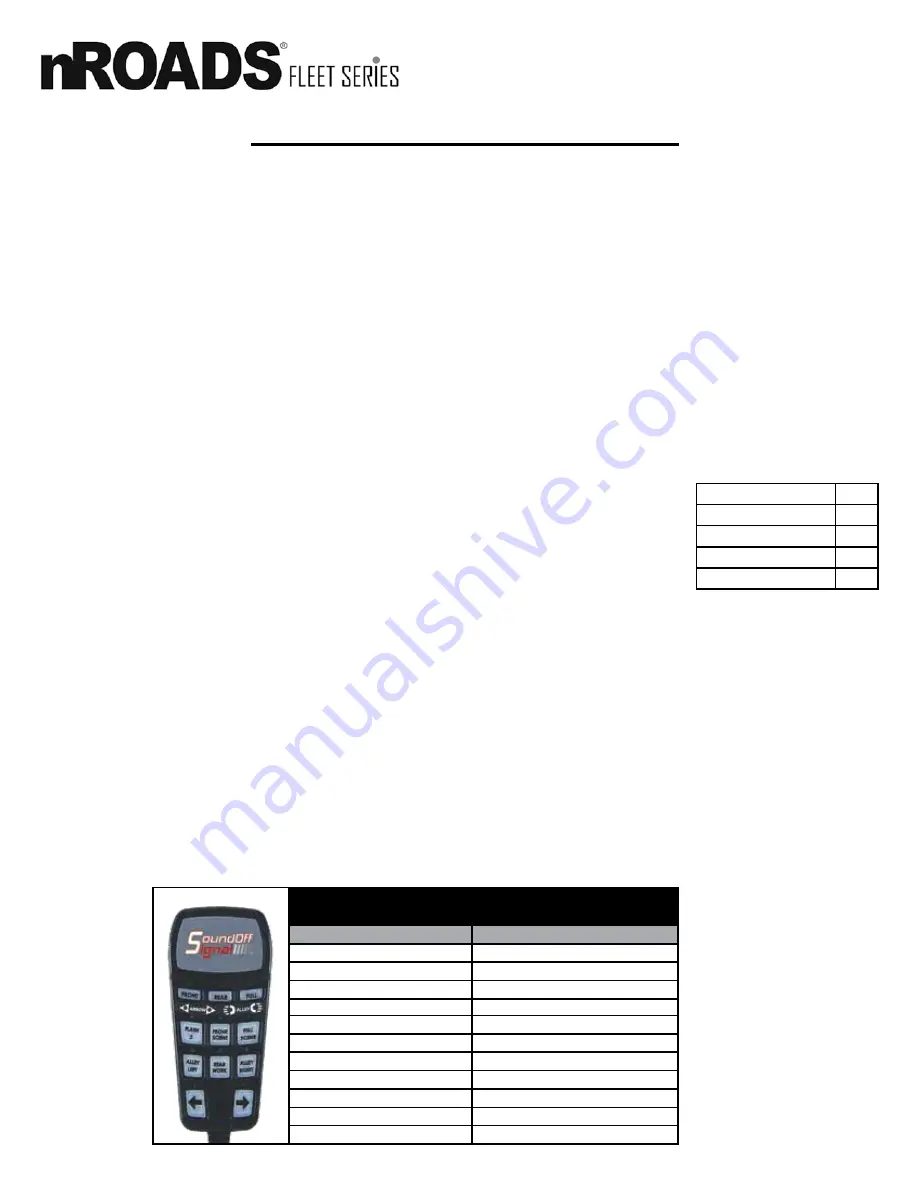
HANDHELD BUTTON ASSIGNMENT
(PROGRAMMING MODE)
Button
Function
Front
Exit Programming Mode
Rear
Return to Previous Programming Mode
Full
Advance to Next Programming Mode
Flash 2*
Button 1
Front Scene
Button 2
Full Scene
Button 3
Alley Left
Button 4
Rear Work
Button 5
Alley Right
Button 6
Arrow Left
Button 7
Arrow Right
Button 8
Program 5 – Bar Flash Colors and Worklight Mode:
1. Press and hold buttons 1 and 6 for 5 seconds.
2. The arrow right and alley right indicators will flash and system will transition to warning mode 1 with worklights modes to indicate system is in this programming
mode.
3. Press button 7 to assign these settings to flash pattern 1. Press button 8 to assign settings to flash pattern 2.
4. The flash pattern colors are selected by buttons 1 and 2, where button 1 will enable color 1, button 2 will enable color 2. Dual color flash mode is activated
when both button 1 and button 2 are selected.
5. The worklight mode is selected with button 4 and 5. Button 4 will enable partial worklight mode and button 5 will enable full worklight mode.
6. Button 6 determines if the worklight modules will flash when bar is configured for partial worklight mode. On = flash, off = don’t flash the worklight color.
7. Press the front button to exit programming mode, rear to decrement to the previous program mode or full to advance to next programming mode.
Program 6 – mpower® Fascia Worklight Color Selection:
1. Press and hold buttons 2 and 3 for 5 seconds.
2. The alley left and alley right indicators will flash and system will transition to scene mode to indicate system is in this programming mode.
3. The worklight color for the front mpower® lights is determined by buttons 1, 2 and 3, where button 1 enables color 1, button 2 enables color 2, and button 3
enables color 3.
4. The worklight color for the rear mpower® lights is determined by buttons 4, 5 and 6, where button 4 enables color 1, button 5 enables color 2, and button 6
enables color 3.
5. Press the front button to exit programming mode, rear to decrement to the previous program mode or full to advance to next programming mode.
*Flash must already be active


