

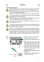


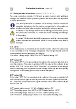

17
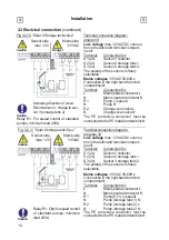
Terminal connection diagram,
program 15
Fig. 3.2.16 “Universal 2x
∆
T controller”
Low voltage
max. 12VAC/DC connec-
tion in the left-hand terminal compart-
ment!
Terminal: Connection
for:
S1 (2x)
Sensor 1 (control)
S2 (2x)
Sensor 2 (ref.+contr.)
S3 (2x)
Sensor 3 (reference)
Caution
Relay R1: Only for speed control
of standard pumps, minimum
load 20VA
The polarity of the sensors is freely
selectable.
Mains voltages
115VAC 50-60Hz
Connection in the right-hand terminal
compartment!
Terminal: Connection
for:
L
Mains phase conductor L
N
Mains neutral conductor N
R1
Pump L (speed)
N
Pump N
R2
e.g. pump L
N
e.g. pump N
The PE protective conductor must be
connected to the PE metal terminal block!
Sensor side
max. 12V
Danger
Caution
Mains side
115VAC
Brief description of switching function:
The
∆
T function sensor 1 > sensor 2
switches the pump to relay R1.
The
∆
T function 2 > sensor 3
switches the pump to relay R2.
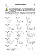
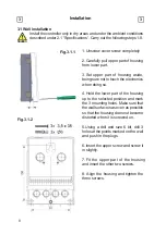
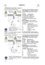
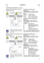
Installation
3
3
3.2 Electrical connection
(continued)
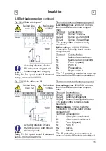
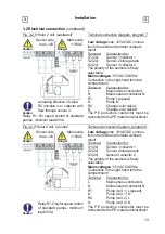
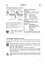
3.3 Installing the temperature sensors
The temperature sensor cables must be routed separately from mains
voltage cables, and must not, for example, be routed in the same cable
duct!
Caution
The controller operates with Pt1000 temperature sensors which
are accurate to the degree, thus ensuring optimal control of system
functions.
Caution
If desired the sensor cables can be extended to a maximum of 30m
using a cable with a cross-section of at least 0.75mm². Make sure that
there is no contact resistance!
Position the sensor precisely in the area to be measured!
Only use immersion, pipe-mounted or
fl
at-mounted sensor suitable
for the speci
fi
c area of application with the appropriate permissible
temperature range.


