Sorel HCC 5 Скачать руководство пользователя страница 32

32

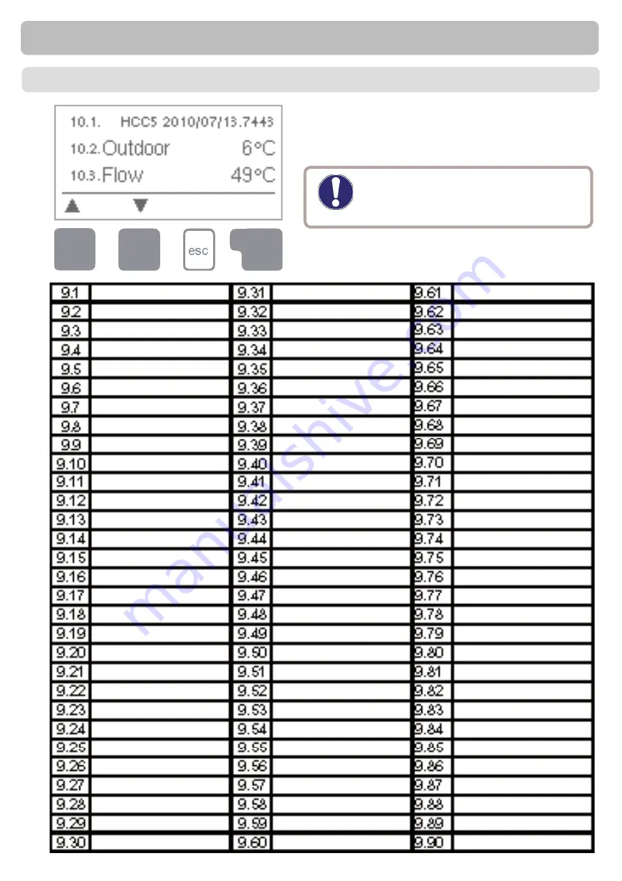
Menu “10. Service values” can be used 
for remote diagnosis by a specialist or the 
manufacturer in the event of an error, etc.

The menu can be closed at any time by 
pressing “esc”.

Service values

10. Service 

values

Caution

Enter the values at the time when 
the error occurs into the table.

Содержание HCC 5

Страница 1: ...Read carefully before installation commissioning and operation Heating Controller HCC 5 Installation and operating instructions Weather controlled heat circuit regulator ...

Страница 2: ... Reset clear 16 3 Times 17 3 1 Time Date 17 3 2 Heating circuit day 17 3 3 Heating comfort 17 3 4 Hot water enable 18 4 Operating modes 19 4 1 Heat circuit 19 4 2 Manual 20 4 3 Heat circuit reference 20 4 4 14 day reference 20 4 5 Domestic Hot Water 20 5 Settings Heating circuit 21 5 1 Su Wi Day 21 5 2 Su Wi Night 21 5 3 Curve 22 5 4 Day correction 23 5 5 Night correction 23 5 6 Comfort temperatur...

Страница 3: ...egulations the regulations of the local power utility the applicable DIN EN standards and the installation and operating instruction of the additional system components must also be observed The controller does not under any circumstances replace any safety devices to be provided by the customer Installation electrical connection commissioning and maintenance of the unit may only be carried out by...

Страница 4: ...and accessories Use of the device for other than its intended purpose Operation above or below the limit values listed in the specifications Force majeure Changes additions to or conversion of the unit are not permitted without written permission from the manufacturer It is likewise forbidden to install additional components that have not been tested together with the unit If it becomes clear that...

Страница 5: ...5 C for transport storage no moisture condensation permitted Other specifications and dimensions Housing design 2 part ABS plastic Installation methods Wall installation optionally panel installation Overall dimensions 163mm x 110mm x 52mm Aperture installation dimensions 157mm x 106mm x 31mm Display Fully graphical display 128 x 64 dots Light diode Multicolour Operation 4 entry keys Temperature s...

Страница 6: ...or ship it back to the seller or manufacturer B 3 About the controller The weather controlled Heat Circuit Controller HCC 5 facilitates efficient use and function control of your heating system The device is impressive most of all for its functionality and simple almost self explanatory operation For each step in the input process the individual entry keys are assigned to appropriate functions and...

Страница 7: ...stalled in an ap propriate position ahead of the mixer B 6 Hydraulic variants Description of controller Caution The following illustrations should be viewed only as schematic dia grams showing the respective hydraulic systems and do not claim to be complete The controller does not replace safety devices under any circumstances Depending on the specific application additional system components and ...

Страница 8: ...uch the electronics when doing so 4 Hold the lower part of the housing up to the selected position and mark the 3 mounting holes Make sure that the wall surface is as even as possible so that the housing does not become distorted when it is screwed on 5 Using a drill and size 6 bit drill 3 holes at the points marked on the wall and push in the plugs 6 Insert the upper screw and screw it in slightl...

Страница 9: ...and side of the unit and mains voltage cables only into the right hand side Caution The customer must provide an all pole disconnecting device e g a heating emergency switch Caution The cables being connected to the unit must not be stripped by more than 55mm and the cable jacket must reach into the housing just to the other side of the strain relief 1 Open controller housing see C 1 1 2 Strip cab...

Страница 10: ...or suitable for the specific area of application with the appropriate permissible tempe rature range Caution S6 is by default connected by jumper with the terminal block S to ena ble the heating circuit functions If the jumper is removed the heating circuit is switched off When connecting the remote adjuster RC21 the jumper has to be removed If a third party external thermostat is con nected it s ...

Страница 11: ...hosen Mains Voltage 230VAC 50 60Hz connec tion in the right hand terminal compartment Terminal Connection for N Jumper terminal block N L Mains phase conductor L R1 Heat circuit pump R2 Mixer open R3 Mixer close R4 Valve DHW pump R5 add heating R5I add heating The PE protective conductor must be connected to the PE metal terminal block Note If the remote adjuster RC21 or a different external float...

Страница 12: ...mode Off is set The LED 2 fl ashes slowly red in the operating mode Manual The LED 2 flashes quickly red when an error is present Entries are made using four keys 3 4 to which different functions are assigned de pending on the situation The esc key 3 is used to cancel an entry or to exit a menu If applicable there will be a request for con firmation as to whether the changes which have been made s...

Страница 13: ...ou back step by step to the selec tion mode thus cancelling the commissioning help Finally menu 4 3 under operating mode Manual should be used to test the switch outputs with the consumers connec ted and to check the sensor values for plausibility Then switch on automatic mode The first time the controller is turned on and after the language and time are set a query appears as to whether you want ...

Страница 14: ...e main menu The following menu items are then availa ble for selection there Current temperature values with explanations Function control of the system with operating hours etc Operatingtimesforheatingcircuitandhotwater settingtheclock Operatingtimesforheatingcircuitandhotwater manualmode Set parameters for the heating circuit Anti seizing protection Frost prot Anti Legionella activation Sensor c...

Страница 15: ...lay instead of the measurement value then there may be a defective or incorrect temperature sensor If the cables are too long or the sensors are not placed optimally the result may be small deviations in the measurement values In this case the display values can be compensated for by making entries on the controller Follow the instructions under 8 1 What measurement values are displayed depends on...

Страница 16: ...p connected to the controller and the date the measurement started 2 4 Operating hours DHW Display of operating hours of Domestic Hot Water pump connected to the controller and the date the measurement started 2 5 Operating hours heating Display of operating hours of additional heating and the date the measurement star ted 2 6 Error messages Display of the last three errors in the system with indi...

Страница 17: ...d temperature settings 3 3 Heating comfort This menu can be used to select a time range for each day of the week in which the heating circuit is supplied with an increased comfort temperature e g for quick heating in the morning Setting range One time range for each day of the week Default Mo Su off Note See 5 for the associated temperature settings Times Caution For proper functioning of the cont...

Страница 18: ...g is enabled sensor 3 three time periods can be specified for each weekday and copied over to the following days Setting range Three time ranges for each day of the week Default Mo Su 6 00 22 00 Note See 11 for the associated temperature settings Caution Times that are not specified are set to disabled ...

Страница 19: ...Fixed flow temperature regardless of the outdoor temperature The desired flow temperature has to be set in menu 4 3 14 day reference value Specific fixed flow temperatures can be set for the next 14 days in menu 4 4 After 14 days the reference temperature of the 14th day is used until the operating mode is changed Off Heating circuit is switched off except Frost protection Settings range Auto Cont...

Страница 20: ...C 4 2 Manual 4 3 Heat circuit reference Danger The operating mode Manual may only be used by specialists for brief function tests e g during commissioning The domestic hot water heating can be activated here Auto makes use of the times set in the times menu see menu 3 4 On activates continuously and Off switches the DHW heating off Settings range Auto On Off Default Auto If operating mode 14 day r...

Страница 21: ...f Summer mode If the outdoor temperature drops below this value the heating circuit is switched on again Winter mode Setting range from 0 C to 30 C default setting 18 C Summer Winterchangeover in nighttime mode If this value is exceeded at outdoor sensor S1 during the nighttime mode times the controller automatically switches the heating circuit off Summer mode If the outdoor temperature drops bel...

Страница 22: ...and finally the steepness of the curve after the split While adjusting the curve the steepness of the slope and the cal culated reference flow temperature for 12 C outdoor temperature is displayed Settings range Characteristic curve simple or split Default simple Slope 0 0 3 0 Default 0 8 Splitpoint at outdoor temp 10 C 10 C Angle differs depends on steepness and split point Settings Heating circu...

Страница 23: ... C 5 4 Day correction Parallel translation of the characteristic curve The night correction produces a parallel translation of the heating characteristic during the nighttime operating hours If a negative value is set for the night correction the re ference flow temperature is lowered accordingly during the nighttime operating hours In this manner primarily at night but also during the day when no...

Страница 24: ...emperature If the heat circuit flow temperature falls below the reference temperature by this value the additional heating R5 is activated after a delay of 1 minute Settings range 10 C to 10 C Default 2 C 5 7 Reference actual Switch off hysteresis only if S4 is connected This settings determines the allowed overstepping of the heat circuit temperature to the calculated reference flow temperature a...

Страница 25: ... heating relay R5 are activated Settings range 10 C to 60 C Default 45 C 6 2 DHW reference Hot water hysteresis The domestic hot water pump relay R4 and and additional heating relay R5 is swit ched off when the temperature at DHW sensor S3 reaches the temperatures set in the menus DHW min and DHW reference plus the temperature difference set here Settings range 2K to 20K Default 10K 6 3 DHW hyster...

Страница 26: ...ng periods of inactivation Settings range on off Default on Frost protection function can be activated for the heat circuit If the outdoor tempera ture at sensor S1 drops below 1 C and the heat circuit is switched off the controller switches the heat circuit back on with the reference temperature set in in menu 6 3 min flow temperature As soon as the outdoor temperature exceeds 1 C the heat circui...

Страница 27: ... water circulation in the storage tank and piping system by means of other additional energy sources and control units Caution Caution Caution This is used as the upper limit for the reference flow temperature of the heat circuit Should the heat circuit temperature exceed this value the heat circuit is switched off until the temperature drops below Settings range 30 C to 105 C Default 45 C When th...

Страница 28: ...rrors Starting the commissioning help guides you in the correct order through the basic set tings necessary for commissioning and provides brief descriptions of each parameter in the display Pressing the esc key takes you back to the previous value so you can look at the selected setting again or adjust it if desired Pressing the esc more than once takes you back to the selection mode thus cancell...

Страница 29: ...lculated pause time of the mixer is multiplied with the value set here If the pause factor is 1 the normal pause time is used 0 5 will use half the normal pause time 4 would quadruple the pause time Settings range 0 1 to 4 0 Default 1 0 8 5 3 Increase If the temperature rises very fast this value is added to the measured flow tempera ture so that the mixer s reaction is stronger If the measured te...

Страница 30: ...s Example Reference roomtemp e g 25 C room temp e g 20 C 5 C deviation calculated reference temp e g 40 C room controller 10 4 C 5 X 4 C 20 C According to this 20 C are added to the reference flow temperature resulting in 60 C If the value is higher than the one set in max flow temp the resul ting temperature is only the one set in max flow temp Settings range 0 to 20 Default 0 8 6 2 Room referenc...

Страница 31: ...ting range on off default setting off Menu 9 Menu lock can be used to secure the controller against unintentional changing and compromise of basic functions The menu is closed by pressing esc or selecting Exit menu lock 9 Menu lock 11 Language Menu 11 Language can be used to se lect the language for the menu guidance This is queried automatically during initial commissioning The choice of language...

Страница 32: ...r remote diagnosis by a specialist or the manufacturer in the event of an error etc The menu can be closed at any time by pressing esc Service values 10 Service values Caution Enter the values at the time when the error occurs into the table ...

Страница 33: ...btain more detailed information on the error press the key under the warning or info symbol Possible error information messages Notes for the specialist Sensor x defective Means that either the sensor the sensor input at the controller or the connecting cable is was defective Resistance table on page 5 Restart Information only Means that the controller was restarted for ex ample due to a power fai...

Страница 34: ... working on the unit switch off the power supply and secure it against being switched on again Check for the absence of power Only use the supplied spare fuse or a fuse of the same design with the following specifications T2A 250V Z 2 Replacing the fuse Z 2 1 Performing maintenance Check the date and time Assess check plausibility of statistics see 2 Check the error memory see 2 6 Verify check pla...

Страница 35: ...x or e mail with a brief description of the error to the specialist or manufacturer The service values see 10 include not only current measurement values and operating states but also all of the settings for the controller Write the service values down just once after commissioning has been successfully completed To protect against loss of data record any statistics and data that are particu larly...

Страница 36: ...ssi ble care the possibility of incorrect or incomplete information cannot be excluded Subject as a basic principle to errors and technical changes Hydraulic variant set Commissioned on Commissioned by Manufacturer SOREL GmbH Mikroelektronik Jahnstr 36 D 45549 Sprockhövel Tel 49 0 2339 6024 Fax 49 0 2339 6025 www sorel de info sorel de ...

Отзывы: