1-8
UP-55MD
BVTT
2.6
x
5
BVTT
2.6
x
5
BVTT2.6
x
5
BVTT2.6
x
5
BVTT
2.6
x
5
BVTT
2.6
x
5
BVTT
2.6
x
5
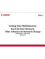
MA shield plate
Mechanical
main unit
assembly
Harnesses
Bottom
stay (L)
Bottom
stay (R)
Switching
regulator
W2.3
W2.3
Pick-up belt
Sensor gear
Tension arm (S) subassembly
Helical extension
spring
Helical extension
spring
Pick-up belt gear
Tension arm
assembly
6.
Remove the four screws, then remove the MA shield
plate.
7.
Disconnect the two harnesses from the switching
regulator.
8.
Remove the six screws, then remove the mechanical
main unit assembly.
9.
Remove the four screws, then remove the bottom stay
(L) and bottom stay (R).
10. Attach the mechanical main unit assembly in the
reverse order of steps 1 to 9.
1-5-3. Stepping Motor
Removal
1.
Remove the top cover. (Refer to Section 1-3-1.)
2.
Remove the front panel assembly.
(Refer to Section 1-3-2.)
3.
Remove the MA-142 board. (Refer to Section 1-4-1.)
4.
Remove the mechanical main unit assembly.
(Refer to Section 1-5-2.)
5.
Remove the MEC-24 board. (Refer to Section 1-4-2.)
6.
Remove the retaining ring, then remove the sensor
gear.
7.
Remove the helical extension spring from the tension
arm assembly.
8.
Remove the helical extension spring from the tension
arm (S) subassembly.
9.
Remove the retaining ring, then remove the pick-up
belt gear and pick-up belt.
Содержание UP55MD
Страница 1: ...COLOR VIDEO PRINTER UP 55MD SERVICE MANUAL Volume 1 1st Edition Revised 2 ...
Страница 4: ......
Страница 8: ......
Страница 30: ......
Страница 38: ......
Страница 48: ......
Страница 52: ......
Страница 72: ......
Страница 74: ...Sony Corporation 2010 7 08 2005 UP 55MD SY E 9 879 778 03 ...