- 13 -
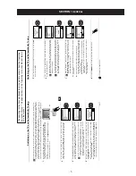
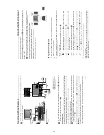
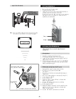
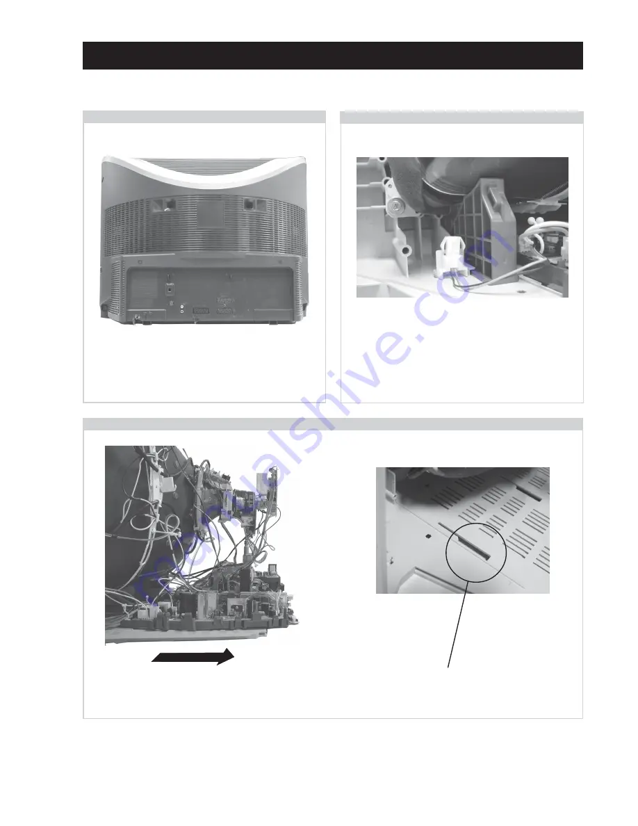
Before completely removing the rear cover disconnect the
speaker connector which is located on the inside of the set.
=>
=>
=>
=>
=>
=>
=>
SECTION 2 DISASSEMBLY
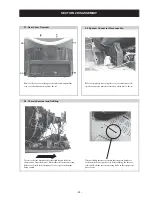
2-1. Rear Cover Removal
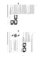
To remove lift the main bracket rear slightly and slide the
chassis away from the beznet. Ensure that the interconnecting
leads are released from their purse locks to prevent damage
being caused.
When refitting the chassis ensure that the main bracket is
located in the beznet guide slots before sliding the chassis
forwards. Refit the inter-connecting leads in their respective
purse locks.
2-3. Chassis Removal and Refitting
2-2. Speaker Connector Disconnection
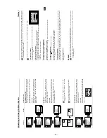
Remove the rear cover fixing screws indicated and pull the
rear cover backwards away from the set.
Содержание Trinitron KV-29XL70K
Страница 34: ...A B C D E F G H I J K L M N 1 2 3 4 5 6 7 8 9 10 11 34 A Printed Wiring Board Conductor side A ...
Страница 35: ...A B C D E F G H I J K L M N 1 2 3 4 5 6 7 8 9 10 11 35 A Printed Wiring Board Conductor side B ...
Страница 39: ...A B C D E F G H I J K L M N 1 2 3 4 5 6 7 8 9 10 11 39 G Board Schematic Diagram Power Supply ...
Страница 40: ...A B C D E F G H I J K L M N 1 2 3 4 5 6 7 8 9 10 11 40 D Board Schematic Diagram Deflection ...
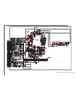
Страница 44: ...A B C D E F G H I J K L M N 1 2 3 4 5 6 7 8 9 10 11 44 M Board Schematic Diagram Micro Processor ...


