


- 14 -
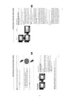
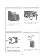
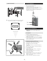
To remove the G Board release the clips circled and ease the
board gently away from the support bracket.
Removal of the D board follows the same procedure.
Clips
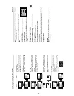
If the M Board needs to be removed for testing when the
chassis is placed in its service position, it would be necessary
to use an extender board and extension cable as indicated
above.
The Extender board and extension cable are available as a
service part by ordering the part number as indicated.
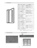
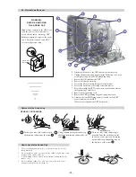
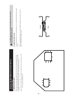
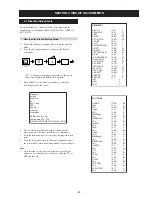
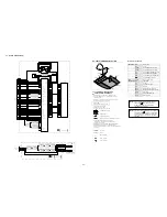
2-6. Service Connector for M Board
To A
Board
From M
Board
Extender Board Assembly A-1642-293-A
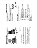
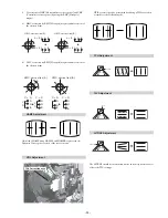
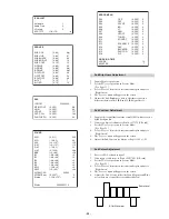
2-7. Wire Dressing
Ensure that wires do not touch heatsinks and high temperature
hotspots. All wires must be kept at a minimum distance of
20mm away from the EHT lead
20mm
20mm
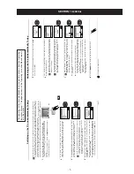
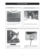
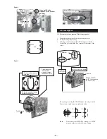
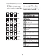
2-4. Service Position
2-5. G Board Removal
To place the chassis in the service position, remove the H
bracket and stand the chassis as shown above. To gain
access to the underside of the boards follow the
instructions on page 16. [Removal and Replacement of the
main bracket bottom plates].
Содержание Trinitron KV-29XL70K
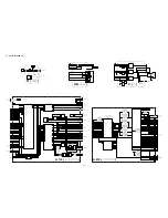
Страница 34: ...A B C D E F G H I J K L M N 1 2 3 4 5 6 7 8 9 10 11 34 A Printed Wiring Board Conductor side A ...
Страница 35: ...A B C D E F G H I J K L M N 1 2 3 4 5 6 7 8 9 10 11 35 A Printed Wiring Board Conductor side B ...
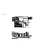
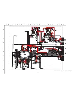
Страница 39: ...A B C D E F G H I J K L M N 1 2 3 4 5 6 7 8 9 10 11 39 G Board Schematic Diagram Power Supply ...
Страница 40: ...A B C D E F G H I J K L M N 1 2 3 4 5 6 7 8 9 10 11 40 D Board Schematic Diagram Deflection ...
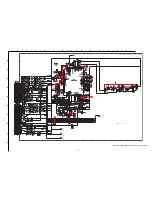
Страница 44: ...A B C D E F G H I J K L M N 1 2 3 4 5 6 7 8 9 10 11 44 M Board Schematic Diagram Micro Processor ...