background image

1-35

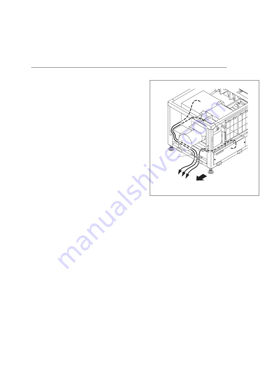
SRX-R320

External device

Hole

Front side

Fig. 1-12

1-12.  Connecting and Wiring of External Device

w

Do not plug the power cord into the power supply when performing the following wiring operations.

Signal cable wiring

When connecting this unit or LMT-300 installed in this unit 
to external device, connect by routing the cable through the 
hole of the front side.

Содержание SRX-R320

Страница 1: ...DIGITAL CINEMA PROJECTOR SRX R320 INSTALLATION MANUAL 1st Edition ...

Страница 2: ...e Angaben in der Anleitung zu befolgen Andere als die angegeben Wartungsarbeiten dürfen nur von Personen ausgeführt werden die eine spezielle Befähigung dazu besitzen AVERTISSEMENT Ce manual est destiné uniquement aux personnes compétentes en charge de l entretien Afin de réduire les risques de décharge électrique d incendie ou de blessure n effectuer que les réparations indiquées dans le mode d e...

Страница 3: ...y 2 37 2 8 How to Use the SRX Controller 2 38 2 8 1 Configuration 2 38 2 8 2 Function Memory 2 38 2 8 3 Functions of Each Window 2 39 3 Error Message Manual Structure Purpose of this manual 3 Related manuals 3 Trademarks 3 1 Installation Outline 1 1 1 1 Removing Installing the Cabinet Panel 1 1 1 1 1 Name of Cabinet Panel 1 1 1 1 2 Panel U7 Block Assembly 1 2 1 1 3 Panel U2 Block Assembly 1 2 1 1 ...

Страница 4: ......

Страница 5: ...t This manual describes the information required for the actual management and op eration of this unit Service Manual available on request This manual describes the information for periodic maintenance and detailed ser vice Trademarks Trademarks and registered trademarks used in this manual are follows Windows and Windows XP are registered trademarks of Microsoft Corporation in the United States a...

Страница 6: ......

Страница 7: ...n of power cord in step 12 before completing steps 1 to 11 Be sure to remove the lamp bulb when moving this unit 1 Adjust the tilt angle Refer to Section 1 2 2 Install the duct Refer to Section 1 3 3 Install the projection lens Refer to Section 1 4 4 Install the lens cover Refer to Section 1 5 5 Install the status light assembly Refer to Section 1 6 6 Install the touch panel adapter Refer to Secti...

Страница 8: ...rection of the arrow with attention to the three hooks 3 To install reverse the removal procedure 1 1 3 Panel U2 Block Assembly 1 Remove the panel U7 block assembly Refer to Section 1 1 2 2 Loosen the two screws with drop safe then remove the two grilles 3 Remove the five screws then raise the panel U2 block assembly in the direction of arrow with atten tion to the twelve hooks 4 Remove the panel ...

Страница 9: ...o Section 1 1 3 3 Remove the three screws then remove the panel U3 in the direction of the arrow 4 To install reverse the removal procedure 1 1 5 Panel U6 1 Remove the panel U7 block assembly Refer to Section 1 1 2 2 Remove the five screws then raise the panel U6 in the direction of arrow with attention to the eleven hooks 3 Remove the panel U6 in the direction of arrow 4 To install reverse the re...

Страница 10: ...e the panel U5 in the direction of arrow 4 To install reverse the removal procedure 1 1 7 Panel U1B 1 Remove the panel U7 block assembly Refer to Section 1 1 2 2 Remove the panel U2 block assembly Refer to Section 1 1 3 3 Remove the panel U6 Refer to Section 1 1 5 4 Remove the six screws then lower the panel U1B in the direction of arrow 5 Remove the panel U1B in the direction of arrow 6 To instal...

Страница 11: ... assembly Refer to Section 1 1 2 2 Remove the panel U2 block assembly Refer to Section 1 1 3 3 Remove the panel U6 Refer to Section 1 1 5 4 Remove the panel U1B Refer to Section 1 1 7 5 Remove the eight screws then remove the panel U1 in the direction of arrow 6 To install reverse the removal procedure ...

Страница 12: ...80 degrees Fig 1 1 9 1 1 9 Panel U4 Block Assembly 1 Release the lock on the panel U4 block assembly 2 Open the panel U4 block assembly at an angle of about eighty degrees 3 Raise to remove the panel U4 block assembly from the two hinge portions 4 To install reverse the removal procedure ...

Страница 13: ...o Section 1 1 3 3 Remove the panel U3 Refer to Section 1 1 4 4 Remove the panel U6 Refer to Section 1 1 5 5 Remove the panel U5 Refer to Section 1 1 6 6 Open the panel U4 block assembly Refer to steps 1 and 2 in Section 1 1 9 7 Remove the four screws then remove the panel U4B in the direction of arrow with attention to the two hooks 8 To install reverse the removal procedure ...

Страница 14: ...2 2 Remove the panel U2 block assembly Refer to Section 1 1 3 3 Remove the panel U3 Refer to Section 1 1 4 4 Remove the panel U6 Refer to Section 1 1 5 5 Remove the panel U5 Refer to Section 1 1 6 6 Remove the two screws then remove the STL cover 7 Remove the eight screws then remove the panel U8 8 To install reverse the removal procedure ...

Страница 15: ...gle Adjustment is required In the case of tilt angle under 5 degrees Adjust the tilt angle using the adjuster in the lower portion of this unit 1 Loosen the nut 2 Adjust the tilt angle by rotating the adjuster in the lower portion of this unit 3 Secure the adjuster by tightening the nut to the adjuster pipe side ...

Страница 16: ...U2 block assembly Refer to Section 1 1 3 3 Remove the panel U3 Refer to Section 1 1 4 4 Remove the panel U6 Refer to Section 1 1 5 5 Remove the panel U5 Refer to Section 1 1 6 6 Set the tools such as jack at both sides of frame then raise the rear portion of the main unit 7 Remove the four M8 bolts 8 Move the adjuster pipe assembly downward and insert the four M8 bolts into the four holes to secur...

Страница 17: ...ustration Part name Anchor BKT optionally available 3 294 224 01 1 3 Installing the Duct Attach the commercially available 8 inch duct to the duct connection of the panel U8 of this unit n When attaching the duct be careful not to bend it so that the exhaust air flows smoothly External fan exhaust air air volume specification The following exhaust air volume is required for the 8 inch duct Exhaust...

Страница 18: ...ns bracket Fig 1 4 1 4 Installing the Projection Lens 1 Attach the projection lens 2 Align the notch of lens bracket with the line of projec tion lens and tighten the supplied four bolts in the order from to 3 Connect the three cables focus zoom and POTEN TIO n Do not attach the lens cover before completing the lens adjustment Refer to Section 2 3 ...

Страница 19: ... 5 Installing the Lens Cover 1 Attach the lens cover in the direction of arrow with attention to the three hooks n The lens covers are same parts so they can be attached both upper and lower 2 Attach the lens cover in the direction of arrow with attention to the three hooks n When attaching the lens cover align the four convex portions with the four holes ...

Страница 20: ...ach the one touch bush supplied with the unit to the hole in the upper area of this unit 4 Route the harnesses through the hole in the upper area of the unit then connect the two harnesses of the status light assembly and the two harnesses of the unit n The tags are attached on the harnesses 4 pin Connect them with the following combination of the indication on the tag Status light side This unit ...

Страница 21: ... the Touch Panel Adapter n The recommended operating monitor manufactured by ADVANTECH can be attached to the supplied touch panel adapter For details contact your local Sony Sales Office Service Center 1 Attach the TPC base to the panel U4B with the six M4 screws 2 Attach the TPC bracket to the operating monitor with the six M3 screws ...

Страница 22: ... Pull the knob of the TPC base in the direction of the arrow then fix it by rotating in the direction of the arrow 4 Attach the operating monitor to the TPC base as shown in the illustration 5 Align the knob with the angular adjustment hole then return the knob to the original position in the reverse order of step 3 ...

Страница 23: ...tection suit kit J 7120 330 A M size J 7120 340 A L size or J 7120 460 A XL size Also wear the shoes that cover the instep of the foot com pletely Be extremely careful when handling the xenon lamp bulb because a high voltage is applied to it Do not touch the lamp bulb with bear hands Otherwise it may break the lamp bulb Wearing of protection suit kit 1 Wear the jacket and trousers 2 Wear the arm c...

Страница 24: ...ich is required for installation Keep the materials such as packaging box case protection sheet because they are used when disposing of the used lamp bulb As for the anode harness integrated lamp bulb steps 1 and 2 are not required 1 Loosen the screw and bend portion A of the anode harness 2 Attach the anode harness to the anode side of the lamp bulb then tighten the screw Tightening torque 1 2 N ...

Страница 25: ...er Panel U4 block assembly Fig 1 8d Fig 1 8e 3 Open the panel U4 block assembly Refer to steps 1 and 2 in Section 1 1 9 4 Loosen the screw with drop safe then rotate the cold mirror assembly in the direction of the arrow 5 Loosen the five screws with drop safe then remove the maintenance cover 6 Remove the bolt from the anode terminal 7 Loosen the hexagon socket set screw of the cathode terminal ...

Страница 26: ...1 20 SRX R320 Plastic cover Lamp bulb Protection sheet Lamp bulb Fig 1 8g Fig 1 8f 8 Remove the plastic cover from the lamp bulb 9 Remove the protection sheet from the lamp bulb ...

Страница 27: ...1 Insert portion A of the lamp into the cathode terminal n When attaching the lamp bulb be careful not to dam age the reflector portion Also be careful not to dam age the glass of lamp bulb Otherwise it may break the lamp bulb 12 Hold the cathode side of the lamp bulb firmly and raise the anode side Then return the anode holder to the original position and tighten the knob ...

Страница 28: ...ulb on the anode holder 14 Attach the anode harness to the anode terminal then tighten the bolt Tightening torque 1 5 N m n After installing the anode harness separated lamp bulb if there is a clearance in portion A of the anode holder adjust it by bending the anode harness so that there is no clearance between the anode holder and the lamp bulb 15 Tighten the hexagon socket set screw of the catho...

Страница 29: ...necting with the Unit 1 Remove the panel U7 block assembly Refer to Section 1 1 2 2 Remove the panel U2 block assembly Refer to Section 1 1 3 3 Remove the panel U6 Refer to Section 1 1 5 4 Remove the panel U1B Refer to Section 1 1 7 5 Loosen the two screws with drop safe then remove the front panel from the LMT 300 ...

Страница 30: ...MT 300 in this unit 7 Secure LMT 300 with the four installation screws B5 x 12 supplied with LMT 300 8 Attach the HDD unit supplied with LMT 300 Refer to LMT 300 Installation Manual 9 Connect the harness of this unit to the STATUS LIGHT connector in the front panel 10 Attach the front panel n Tighten the screws with drop safe Tightening torque 0 8 N m ...

Страница 31: ...Screw Screws LMT duct A Power cord Notch Fig 1 9c 11 Attach the power cord to LMT 300 12 Attach the LMT duct A with the screw n When attaching the LMT duct A route the power cord through the notch 13 Attach the LMT duct B with the three screws ...

Страница 32: ...n codes 15 Connect the network connector of this unit with the PRJ CTRL connector of LMT 300 using the supplied LAN cable 16 Connect the connector CN6 on the CN 3225 board of this unit with the CSS connector of LMT 300 using the supplied CSS cable 17 Attach the panel U1B in the reverse order of step 4 18 Attach the panel U6 in the reverse order of step 3 19 Attach the panel U2 block assembly in th...

Страница 33: ...e installing procedure for each slot is same n For INPUT A slot LKRI 005 is installed before shipment Replace it as necessary Parts information Fixed Plate HIF 320 4 159 161 01 For LKRI 003 Fixed Plate DIF 320 4 159 162 01 For LKRI 005 Handle 3 172 089 01 Using 2 pcs Procedure LKRI 003 1 Remove the six screws then remove the panel HIF 44 and finger holder HIF 2 Attach the fixed plate HIF 320 using...

Страница 34: ...Blank panel Fig 1 10c Fig 1 10d 4 Remove the two screws then remove the blank panel n Store the removed blank panel 5 Remove the ten screws then remove the panel cover IF 6 Insert the LKRI 003 board into INPUT B slot and connect it securely 7 Attach the panel cover IF using the twelve screws ...

Страница 35: ... 1 10f Fig 1 10g Procedure LKRI 005 1 Remove the two screws then remove the panel DIF 188 and finger holder DIF 2 Attach the fixed plate DIF 320 using the two screws removed in step 1 3 Attach the two handles to the fixed plate DIF 320 4 Remove the two screws then remove the blank panel n Store the removed blank panel 5 Remove the ten screws then remove the panel cover IF ...

Страница 36: ...1 30 SRX R320 INPUT B LKRI 005 PSW4 x 10 Panel cover IF Fig 1 10h 6 Insert the LKRI 005 board into INPUT B slot and connect it securely 7 Attach the panel cover IF using the twelve screws ...

Страница 37: ... the plug securely Incomplete connection may cause an image trouble When disconnecting the plug be sure to hold the plug with your hand Refer to the Operating Instructions of the equipment to be connected In case of LKRI 003 Input BNC type 2 HD SDI Serial digital 1 485 Gbps Compliant to SMPTE 292M ITU R BT709 BTA S004 Dual link HD SDI Serial digital 1 485 Gbps Compliant to SMPTE 372M DC SDI Serial...

Страница 38: ... DVI D terminal 10 bit signal of its own specification During input 10 bit twin mode Signal level Full Range DVI D terminal and AUX terminal 10 bit signal of its own specification During input 10 bit single mode Signal level Full Range DVI D terminal Used during signal input of DTV standard DVI1 0 compliant Signal level Limited Range DVI D terminal 10 bit signal of its own specification During inp...

Страница 39: ...erlock Terminal Pin location Interlock terminal 1 Interlock Function The SRX R320 interlock function is enabled by making the two pins of the interlock terminal open or short The following two patterns can be used for the interlock function in the applicable serial Pattern 1 Normal Open Interlock Short Open short between pin 4 and pin 5 ...

Страница 40: ...normally open and normally closed by selecting the pins n The relay for external fan control is used for switching the ON OFF control signals for fan The driving current of fan is not switched PIN assign Pin Signal name Function Pin 7 RELAY1_A make contact Pin 8 RELAY1_B break contact Pin 9 RELAY1_C transfer contact Operation table Operation terminal Operating state STANDBY POWER ON RELAY1_C 5 REL...

Страница 41: ...g of External Device w Do not plug the power cord into the power supply when performing the following wiring operations Signal cable wiring When connecting this unit or LMT 300 installed in this unit to external device connect by routing the cable through the hole of the front side ...

Страница 42: ...nd the electric wiring work should be done by qualified electricians only Do not plug the power cord into the power supply before completing all of the following connecting op erations 1 Remove the two screws 2 Remove the terminal block cover with attention to the two hooks 3 Remove the screw then remove the cable clamp 4 Remove the screw then remove the ground terminal Screws Hooks Terminal block...

Страница 43: ... 1 13d 5 Pack by soldering the end of the ground wire 6 Attach the ground terminal removed in step 4 to the ground wire then fix it with the screw 7 Route the cable through the lower hole of the terminal block then fix each terminal by screw 8 Fix the cable with the cable clamp and screw 9 Attach the terminal block cover ...

Страница 44: ...1 38 SRX R320 1 14 Dimensions Front Left Exhaust Barycentric position Barycentric position ...

Страница 45: ...Intake Signal cable For the unit fixing AC power cable Intake Exhaust Intake Intake Intake Optional lens LKRL LIST Barycentric position Barycentric position Barycentric position Refer to List Barycentric position Panel for lamp replacing Unit mm ...

Страница 46: ......

Страница 47: ...ENT TOOL Refer to Technical Manual of SRX R220 6 Set the illuminance of a screen and perform color characteristic tone correction CSC adjustment Refer to Section 2 5 2 Perform the optical axis adjustment of a lamp Perform calibration Refer to Section 2 2 3 Adjust a lens Refer to Section 2 3 8 Set function memory Refer to Section 2 7 7 Adjust the field angle Refer to Section 2 6 Adjustment is perfo...

Страница 48: ...S recommended RAM capacity 256 MB or more 512 MB or more recommended and OS recommended Communication RS 232C 10BASE T 100BASE T Graphics mode XGA 1024 x 768 or higher HDD Built in Drive having an empty capacity of 10 MB or more CD ROM drive Eight times normal speed or faster OS Microsoft Windows XP Professional SP2 except for x64 Edition Cable COM RS 232C cross cable Installation 1 Connect each e...

Страница 49: ... click the radio button for I accept the terms in the license agreement Click the Next button 7 Select the folder in which an SRX Controller is installed Click the Next button if there is no problem in the displayed folder To change the folder to save an SRX Controller click the Change button and select the desired folder ...

Страница 50: ...low is displayed Installation is completed n Click the check box for Launch SRX Controller specialized for DC Projector series when directly starting an SRX Controller in this case 10 Click the Finish button The shortcut of an SRX Controller is displayed on the desktop window 2 1 2 Connection n When performing the adjustment using the RS 232C terminal connect nothing to the NETWORK termi nal of th...

Страница 51: ...op window 4 Click the COM radio button from the Connection menu COM selection Enter the COM port No to be used 5 Select the adjustment menu Login to be used in a Login menu The three adjustment menus below are available User Can check the signal input to this unit or adjust an image Maintenance Can set a lamp or adjust an image in details Installer Can check and change the contents of setting duri...

Страница 52: ...1 3b Fig 2 1 3c Fig 2 1 3d n Window of each adjustment menu Window example Login by User FUNCTION MEMORY window Window example Login by Maintenance MAINTENANCE window Window example Login by Installer INSTALLATION window ...

Страница 53: ... window is displayed 8 Set the items in Internet Setting and Time Setting menus Refer to 5 INSTALLATION window in Section 2 8 3 9 Enter the serial code of the lamp bulb to be installed Refer to steps 1 to 4 in Section 2 2 2 1 4 Startup of This Unit Procedure 1 Turn on the power switch on the rear of this unit Standby state ...

Страница 54: ... 2 1 3 n This procedure is common in the adjustment menu of User Maintenance and Installer 3 Click the ON button of POWER The startup of this unit is completed 2 2 Optical Axis Adjustment of Lamp Procedure 1 Be sure to click the MAINTENANCE tab in the standby state 2 Click the RESET button in a LAMP TIMER RESET menu ...

Страница 55: ...ode box and click the CHECK button m Be sure to perform in the standby state Refer to step 1 in Section 2 1 4 Enter the serial code with the space not put 4 Click the CLOSE button and close the LAMP INFORMATION window 5 Click the ON button of POWER 6 Click the FUNCTION MEMORY tab 7 Set the lamp power to 100 in the LAMP POWER menu to project an image in 100 black No signal condition ...

Страница 56: ...A lamp bulb is not installed when this unit is shipped from the factory Therefore an F34 F35 ADJUST MENT ERROR message may be displayed on the status message display and SRX Controller at the rear of this unit before this adjustment is performed This message disappears when you press the Save button after Z axis adjustment 11 In the same way adjust the X axis and Y axis direction adjusting screws ...

Страница 57: ...ion of an output value press the CALIBRATE button about once a week n This function is enabled when Lamp Control Mode is set to Luminance It is set to Lamp Power in the initial setting Refer to 5 INSTALLATION window in 2 8 3 Function of Each Window 2 3 Lens Adjustment H Shift V Shift Zoom and Focus Adjustments n For further adjustment 2 6 Field Angle Adjustment is required Procedure 1 Project a te...

Страница 58: ...tons in the Lens Control menu on the FUNCTION MEMO RY window Refer to 2 FUNCTION MEMORY window in 2 8 3 Function of Each Window n Set the V shift amount within 1 2 screen If it exceeds 1 2 screen the zoom is changed the image position may not be positioned at same place Check if the V shift amount exceeds 1 2 screen in the following procedure When the V shift amount exceeds 1 2 screen perform the ...

Страница 59: ...stment 2 4 1 Illumination Area Adjustment If there is any deviation of illumination range when installing the unit perform adjustment in the follow ing procedure n The adjustment cannot be correctly performed with the filter cover open because the filter cover switch sensor function operates Before starting the adjustment be sure to close the filter cover after removing the panel duct covers 1 and...

Страница 60: ...dure 1 Remove the panel U7 block assembly Refer to Section 1 1 2 2 Remove the panel U2 block assembly Refer to Section 1 1 3 3 Remove the filter 4 Remove the five screws Fig 2 4 1b Filter center portion Screws Front side ...

Страница 61: ... panel duct cover 1 upper 8 Remove the panel duct cover 2 lower and the panel duct cover 1 lower in the same procedure as steps 6 and 7 9 Close the filter cover then secure it with the screw Fig 2 4 1c Panel duct cover 2 upper Panel duct cover 2 lower Filter cover Panel duct cover 1 upper Screws Screws Panel duct cover 1 lower Front side Filter cover Secure with the screw ...

Страница 62: ...RX R320 10 Start the SRX Controller Refer to Section 2 1 3 11 Click the FUNCTION MEMORY tab FUNCTION MEMORY window MAINTENANCE window TEST PATTERN menu Fig 2 4 1e LENS CONTROL menu LAMP POWER menu Fig 2 4 1d ...

Страница 63: ...e FUNCTION MEMORY window In the case of out of focus adjust it in the same way Refer to 2 FUNCTION MEMORY window in 2 8 3 Functions of Each Window 14 Perform steps 15 to 17 immediately after step 13 is finished 15 Observe the left right top and bottom edges of the screen precisely 16 Check the deviation of illumination range colored area around the white image If there is an area colored by cyan l...

Страница 64: ...t the color space with the unit installed Color space converter The color space converter can correct the color characteristics of this unit 709 Virtual White and DCDM for each color reproduction range Correction of color space 709 Procedure 1 Display the FUNCTION MEMORY window of the SRX Controller Refer to Section 2 1 3 2 Click the radio button of Input A in the INPUT CONTROL menu 3 Display the ...

Страница 65: ...proxi mately 16 ft L the illuminance to be set approximately 2 ft L 8 Select 6500 in Color Temp of the COLOR menu n When the item is not a available input a video signal 9 Select 709 in Color Space of COLOR menu n When the item is not a available input a video signal n Each value is automatically displayed in the Target Color Gamut column of the COLOR SPACE window on the MAINTENANCE tab Moreover r...

Страница 66: ...t pattern of Gray 8 is displayed 16 Measure x y and luminance level Y 17 Enter the measurement result in step 14 into the Input Color Measurement column 18 Click the CALC button 19 Confirm that the differences of all numeric values are less than 0 002 n When there is an item in which the differences of the numeric value is 0 002 or more repeat the steps 14 to 18 20 Click the APPLY button 21 Return...

Страница 67: ...ite The adjustment can be performed in the following two methods Procedure Adjustment using internal test pattern The adjustment can be performed using the internal test patterns Red 1 Green 1 Blue 1 and Gray 8 1 Start the SRX Controller Refer to Section 2 1 3 2 Click the MAINTENANCE tab of the SRX Controller The MAINTENANCE window is displayed 3 Click the ADJUST button in the COLOR SPACE CONVERTE...

Страница 68: ...x and y values in Input Color Measurement in the COLOR SPACE menu 12 Click the CALC button first and then click the APPLY button on the COLOR SPACE window 13 Select Red 1 Green 1 Blue 1 and Gray 8 respectively in the TEST PATTERN SELECT menu Then measure the x and y values respectively and compare the results with the following specifications within an error range of 0 006 x y Red 1 0 680 0 320 Gr...

Страница 69: ...r local Sony Sales Office Service Center 2 Create the Sony_Color_Patch folder and move all files obtained by decompressing the zip file to the Sony_Color_Patch folder The files having the extension of xml and mxf 3 Import it in the same way as the normal DCP contents 4 Start the SRX Controller and the Screen Management Controller 5 Click the FUNCTION MEMORY tab of the SRX Controller The FUNCTION M...

Страница 70: ...r Patch signal from LMT 300 by Screen Management Control ler 9 Click the FUNCTION MEMORY tab of the SRX Controller The FUNCTION MEMORY window is displayed 10 Measure the luminance of screen and adjust the lamp power in the LAMP POWER menu so that the luminance is 16 ft L n After the CSC adjustment the luminance is lowered by approximately 2 ft L 11 Click the MAINTENANCE tab of the SRX Controller T...

Страница 71: ...tively 17 Enter the x and y values in Input Color Measurement on the COLOR SPACE window 18 Click the CALC button first and then click the APPLY button 19 Reproduce the Red 1 Green 1 Blue 1 and Gray 8 of Sony Color Patch signal from LMT 300 by Screen Management Controller Then measure the x and y values respectively and compare the results with the following DCI speci fications within an error rang...

Страница 72: ...PACE menu Fig 2 5l Adjustment of color space DCDM The adjustment can be performed using the internal test patterns Red 1 Green 1 Blue 1 and Gray 8 Procedure 1 Start the SRX Controller Refer to Section 2 1 3 2 Click the MAINTENANCE tab of the SRX Controller The MAINTENANCE window is displayed 3 Click the ADJUST button in the COLOR SPACE CONVERTER menu The COLOR SPACE window is displayed ...

Страница 73: ...d 1 0 680 0 320 Green 1 0 265 0 690 Blue 1 0 150 0 060 Gray 8 0 314 0 319 n If the specifications are not satisfied perform steps 4 5 and 9 to 12 again 14 Select the Gray 10 in the TEST PATTERN SELECT menu 15 Click the FUNCTION MEMORY tab The FUNCTION MEMORY window is displayed 16 Adjust the lamp power in the LAMP POWER menu so that the luminance is 14 ft L n In this procedure the luminance is not...

Страница 74: ...ngle of screen is changed in the horizontal direction Preparation The adjustment method varies depending on whether the V shift amount required for the field angle adjustment is more or less than 1 2 screen Check the required V shift amount before adjustment 1 Fix the H shift at the center 2 Project the Scope Flat pattern 3 Adjust to the field angle of Flat using the zoom focus and V shift When th...

Страница 75: ...Y tab The FUNCTION MEMORY window is displayed 10 Set the masking in the MASKING ADJUST menu Refer to 2 MASKING ADJUST in Section 2 8 3 11 Click the SELECT button 12 Check the FUNCTION MEMORY No and then click the APPLY button Memory of Function Scope adjustment 1 Start the SRX Controller Refer to Section 2 1 3 2 Click the FUNCTION MEMORY tab The FUNCTION MEMORY window is displayed 3 Click the SELE...

Страница 76: ...performed correctly 9 Click the MAINTENANCE tab The MAINTENANCE window is displayed 10 Adjust the luminance using the required test pattern in the TEST PATTERN menu 11 Click the FUNCTION MEMORY tab The FUNCTION MEMORY window is displayed 12 Set the masking in the MASKING ADJUST menu Refer to 2 MASKING ADJUST in Section 2 8 3 13 Click the SELECT button 14 Check the FUNCTION MEMORY No and then click...

Страница 77: ... to Section 2 7 4 Call the FUNCTION MEMORY No for performing the Flat setting using the RECALL button 5 Adjust the zoom and focus in the LENS CONTROL menu and the V shift and H shift refer to Section 2 3 according to the field angle of Flat For the LENS CONTROL menu refer to 2 FUNCTION MEMORY window in Section 2 8 3 n When the projection angle is insufficient adjust the image position in the verti...

Страница 78: ...ION MEMORY No for performing the Scope setting using the RECALL button 5 Adjust the image size focus and image position using the zoom and focus in the LENS CONTROL menu and the electric V shift in the ELECTRIC V SHIFT FUNCTION menu Refer to 2 FUNCTION MEMORY window in Section 2 8 3 6 Click the MAINTENANCE tab The MAINTENANCE window is displayed 7 Adjust the luminance using the required test patte...

Страница 79: ...CTION MEMORY window in 2 8 3 Functions of Each Window INPUT CONTROL LAMP POWER 1 COLOR _ Color Space _ Color Temp _ Gamma PICTURE CONTROL _ Signal Source Signal Mode I P Mode _ Signal Adjust Contrast Brightness Color Sharpness MASKING ADJUST ANAMORPHIC MODE ELECTRIC V SHIFT FUNCTION LENS CONTROL _ ZOOM _ FOCUS 1 Setting of lamp power After the zoom adjustment of a lens adjust using lamp power so t...

Страница 80: ...he left of the number indicates that the number is recalled Fig 2 7 1c 2 Click the SELECT button on the FUNCTION MEMORY window 3 Click the setting No you want to register and enter a name 4 Click the APPLY button after entering the name n If you cannot click the APPLY button set LUMINANCE CONTROL to 0 ...

Страница 81: ...Change in Setting of Registered Function Memory 1 Click the SELECT button from the FUNCTION MEMORY window 2 Click the function memory No you want to change then click the RECALL button to call memory 3 Change the item you want to change and click the SELECT button 4 Confirm the function memory No and click the APPLY button n If you cannot click the APPLY button set LUMINANCE CONTROL to 0 ...

Страница 82: ... Function Memory to Create New Function Memory 1 Click the SELECT button from the FUNCTION MEMORY window 2 Click the function memory No you want to copy then click the RECALL button to call memory 3 Change the item you want to change and click the SELECT button 4 Click the setting No you want to register enter a name and click the APPLY button n If you cannot click the APPLY button set LUMINANCE C...

Страница 83: ...e left of the number indicates that the number is recalled RECALL button CLOSE button Fig 2 7 4b 2 7 4 Switching of Registered Function Memory 1 Click the SELECT button from the FUNCTION MEMORY window 2 Click the setting No you want to switch 3 Click the RECALL button 4 Click the CLOSE button ...

Страница 84: ...in Section 2 8 3 FUNCTION FOR 3D window Refer to 3 in Section 2 8 3 MAINTENANCE window Refer to 4 in Section 2 8 3 INSTALLATION window Refer to 5 in Section 2 8 3 2 8 2 Function Memory In the SRX Controller a total of 20 setting values for both 2D and 3D can be registered In an initial value the setting value is automatically memorized to No 1 To register the setting value in another No click the ...

Страница 85: ...ntrols brightness without using the setting of function memory Function memory cannot be used when this function is used button Luminance increases _ button Luminance decreases Lamp Time Operation Time Warning Info Lamp Time Displays the operation time of a lamp Operation Time Displays the operation time of this unit Warning Info Displays the contents of warning STANDBY LAMP OFF POWER ON STANDBY P...

Страница 86: ...rd default or optional board Input B Input from the optional board Input C Input from LMT 300 LAMP POWER Can adjust the output of a light source lamp in units of 1 between 50 and 100 The screen becomes dark when a numeric value decreases In this case however the power consumption decreases and the life of a lamp becomes long button The numeric value increases _ button The numeric value decreases n...

Страница 87: ...rforms the selection of an input signal or the adjustment of picture quality Signal Source Signal Mode Select the input signal from the equipment selected using INPUT CONTROL n If the setting of Signal Mode does not correspond to the input signal the tone is not correctly displayed and the black is displayed grayly I P Mode Select an I P conversion mode Select Interlace PsF and 1080 50p 60p accord...

Страница 88: ...ing point is double clicked the adjustment window is displayed A setting value increases when you click the button A numeric value decreases when you click the _ button The numeric value can also be entered directly Each setting value is as follows to 0 to 950 _500 to 500 n After the adjusting of adjusting point to is completed perform the adjusting of adjusting point and All items in a MASKING AD...

Страница 89: ... size of an image An image is expanded when you click the button It is reduced when you click the _ button FOCUS Adjusts a focus A focus is adjusted to the distance place when you click the button It is adjusted to the nearby place when you click the _ button ELECTRIC V SHIFT FUNCTION Adjusts the vertical position of the projection screen electrically The screen moves upwards when a setting value ...

Страница 90: ...2 44 SRX R320 Fig 2 8 3f 3 FUNCTION FOR 3D window This function is used for adjustment of 3D lens For this function refer to the INSTALLATION AND SERVICE MANUAL of LKRL A002 A003 ...

Страница 91: ... FILTER TIMER MAINTENANCE TIMER COLOR SPACE CONVERTER Refer to Section 2 5 GHOST BUSTERS TEST PATTERN WHITE BALANCE Changes the Custom1 to Custom4 values of Color Temp in the COLOR menu on the FUNCTION MEMORY window m This menu is displayed only when Custom1 to Custom4 of Color Temp is selected The value changed here is reflected on only Color Temp ...

Страница 92: ...moves by two pixels maximum one pixel at a time when you click the _ button G Green pixels vertically moves by two pixels maximum one pixel at a time when you click the _ button B Blue pixels vertically moves by two pixels maximum one pixel at a time when you click the _ button VERSION INFORMATION Displays the version of this unit Click the VERSION button LAMP TIMER Resets the operation time of a ...

Страница 93: ...or this function refer to the INSTALLATION AND SERVICE MANUAL of LKRL A002 A003 TEST PATTERN An image can be adjusted by projecting the test pattern built in this unit on the screen without inputting the signal from other equipment Each test pattern is as follows Cross Hatch Cross Hatch Invert Checker Flag Scope Flat Test Mode 1 Select Off when not projecting a test pattern on the screen m A COLOR...

Страница 94: ...on Time Zone Sets the area in which this unit is installed Click the check box for Adjust clock for daylight saving changes when setting summer time Date Time Date Sets the date Time Sets the time Time Server NTP Server Enter the address of a network time server in the Address column Lamp Control Mode Selects the Lamp Control Mode Lamp Power The lamp wattage is stored in the Function memory Lumina...

Страница 95: ... of risk high WARNING degree of risk middle and FAILURE degree of risk low according to the degree of risk Take proper measures according to the message number and the remedy n For WARNING degree of risk middle and FAILURE degree of risk low the power is not automati cally turned off during operation of the main unit during projection However take proper measures according to the remedy when the p...

Страница 96: ...onnected Check the LPD board ALERT_15 BOARD DETACHED The CT board is disconnected Check the CT board ALERT_16 BOARD DETACHED The DST board is disconnected Check the DST board ALERT_17 BOARD DETACHED The PR1 board is disconnected Check the PR1 board ALERT_18 BOARD DETACHED The PR2 board is disconnected Check the PR2 board ALERT_19 TEMPERATURE ERROR The unit stops operation by temperature abnormalit...

Страница 97: ...1 is abnormal Check the power fan 1 Replace the power fan 1 if it is damaged WARN_02 FAN ERROR The power fan 2 is abnormal Check the power fan 2 Replace the power fan 2 if it is damaged WARN_05 FAN ERROR The board fan 1 is abnormal Check the board fan 1 Replace the board fan 1 if it is damaged WARN_06 FAN ERROR The board fan 2 is abnormal Check the board fan 2 Replace the board fan 2 if it is dama...

Страница 98: ...rmality of the 8 inch duct Check the outside air temperature the suction amount of a 8 inch duct and the lamp cooling fans FAIL_04 TEMPERATURE ERROR Intake temperature is abnormal Check the outside air temperature FAIL_06 TEMPERATURE ERROR The optical unit block temperature is abnormal Check the outside air temperature and air supply and exhaust FAIL_10 TEMPERATURE ERROR Warning for temperature ab...

Страница 99: ...E ERROR I2 C communication error Turn off the power once then turn on it again FAIL_27 DEVICE ERROR LVDS error Turn off the power once then turn on it again FAIL_28 DEVICE ERROR PLL error Turn off the power once then turn on it again FAIL_29 DEVICE ERROR Parity error Turn off the power once then turn on it again FAIL_30 BALLAST ERROR The power unit for lamp is interlocked Turn off the power once t...

Страница 100: ...0 n Fan location Top view 7 Front side Lamp fan A Lamp fan B Lamp fan C Lamp fan D Peltier R fan Peltier G fan Peltier B fan DST board Filter cover PBS fan PS converter fan 1 CN board PS converter fan 2 Front side ...

Страница 101: ...t of the Free Software Foundation s software and to any other program whose authors commit to using it Some other Free Software Foundation software is covered by the GNU Library General Public License instead You can apply it to your programs too When we speak of free software we are referring to freedom not price Our General Public Licenses are designed to make sure that you have the freedom to d...

Страница 102: ...itation in the term modification Each licensee is addressed as you Activities other than copying distribution and modification are not covered by this License they are outside its scope The act of running the Program is not restricted and the output from the Program is covered only if its contents constitute a work based on the Program independent of having been made by running the Program Whether...

Страница 103: ...m on a volume of a storage or distribution medium does not bring the other work under the scope of this License 3 You may copy and distribute the Program or a work based on it under Section 2 in object code or executable form under the terms of Sections 1 and 2 above provided that you also do one of the following a Accompany it with the complete corresponding machine readable source code which mus...

Страница 104: ...for enforcing compliance by third parties to this License 7 If as a consequence of a court judgment or allegation of patent infringement or for any other reason not limited to patent issues conditions are imposed on you whether by court order agreement or other wise that contradict the conditions of this License they do not excuse you from the conditions of this License If you cannot distribute so...

Страница 105: ...on For software which is copyrighted by the Free Software Foundation write to the Free Software Foundation we sometimes make exceptions for this Our decision will be guided by the two goals of preserving the free status of all derivatives of our free software and of promoting the sharing and reuse of software generally NO WARRANTY 11 BECAUSE THE PROGRAM IS LICENSED FREE OF CHARGE THERE IS NO WARRA...

Страница 106: ...ce Suite 330 Boston MA 02111 1307 USA Also add information on how to contact you by electronic and paper mail If the program is interactive make it output a short notice like this when it starts in an interactive mode Gnomovision version 69 Copyright C year name of author Gnomovision comes with ABSOLUTELY NO WARRANTY for details type show w This is free software and you are welcome to redistribute...

Страница 107: ... you are informed that you can do these things To protect your rights we need to make restrictions that forbid distributors to deny you these rights or to ask you to surrender these rights These restrictions translate to certain responsibilities for you if you distribute copies of the library or if you modify it For example if you distribute copies of the library whether gratis or for a fee you mu...

Страница 108: ...se a particular library in non free programs enables a greater number of people to use a large body of free software For example permission to use the GNU C Library in non free programs enables many more people to use the whole GNU operating system as well as its variant the GNU Linux operating system Although the Lesser General Public License is Less protective of the users freedom it does ensure...

Страница 109: ...ded that you also meet all of these conditions a The modified work must itself be a software library b You must cause the files modified to carry prominent notices stating that you changed the files and the date of any change c You must cause the whole of the work to be licensed at no charge to all third parties under the terms of this License d If a facility in the modified Library refers to a fu...

Страница 110: ...rms of Sections 1 and 2 above on a medium customarily used for software interchange If distribution of object code is made by offering access to copy from a designated place then offering equivalent access to copy the source code from the same place satisfies the requirement to distribute the source code even though third parties are not compelled to copy the source along with the object code 5 A ...

Страница 111: ...ons files in the Library will not necessarily be able to recompile the application to use the modified definitions b Use a suitable shared library mechanism for linking with the Library A suitable mechanism is one that 1 uses at run time a copy of the library already present on the user s computer system rather than copying library functions into the executable and 2 will operate properly with a m...

Страница 112: ...e Library the recipient automatically receives a license from the original licensor to copy distribute link with or modify the Library subject to these terms and conditions You may not impose any further restrictions on the recipients exercise of the rights granted herein You are not responsible for enforcing compliance by third parties with this License 11 If as a consequence of a court judgment ...

Страница 113: ...e incompatible with these write to the author to ask for permission For software which is copyright ed by the Free Software Foundation write to the Free Software Foundation we sometimes make exceptions for this Our decision will be guided by the two goals of preserving the free status of all derivatives of our free software and of promoting the sharing and reuse of software generally NO WARRANTY 1...

Страница 114: ...lic License as published by the Free Software Foundation either version 2 1 of the License or at your option any later version This library is distributed in the hope that it will be useful but WITHOUT ANY WARRANTY without even the implied warranty of MERCHANTABILITY or FITNESS FOR A PAR TICULAR PURPOSE See the GNU Lesser General Public License for more details You should have received a copy of t...

Страница 115: ...em as the need arises However pre or WIP indicates that this release is under development and available for ALPHA testing So for your protection as much as mine I d rather not have it appear in a some distribution especially not a CD ROM distribution The most recent officially distributed version can be found at http e2fsprogs sourceforge net If you need to make a distribution that s the one you s...

Страница 116: ...l Public License as published by the Free Software Foundation either version 2 of the License or at your option any later version This program is distributed in the hope that it will be useful but WITHOUT ANY WARRANTY without even the implied warranty of MERCHANTABILITY or FITNESS FOR A PARTICULAR PURPOSE See the GNU General Public License for more details You should have received a copy of the GN...

Страница 117: ...wing acknowl edgement This product includes software developed by the University of California Berkeley and its contributors 4 Neither the name of the University nor the names of its contributors may be used to endorse or promote products derived from this software without specific prior written permission THIS SOFTWARE IS PROVIDED BY THE REGENTS AND CONTRIBUTORS AS IS AND ANY EX PRESS OR IMPLIED ...

Страница 118: ...ice this list of conditions and the following disclaimer in the documentation and or other materials provided with the distribution THIS SOFTWARE IS PROVIDED BY THE AUTHOR AND CONTRIBUTORS AS IS AND ANY EXPRESS OR IMPLIED WARRANTIES INCLUDING BUT NOT LIMITED TO THE IMPLIED WARRANTIES OF MERCHANTABILITY AND FITNESS FOR A PARTICULAR PURPOSE ARE DISCLAIMED IN NO EVENT SHALL THE AUTHOR OR CONTRIBUTORS...

Страница 119: ...thout prior written permission For written permission please contact openssl core openssl org 5 Products derived from this software may not be called OpenSSL nor may OpenSSL appear in their names without prior written permission of the OpenSSL Project 6 Redistributions of any form whatsoever must retain the following acknowledgment This product includes software developed by the OpenSSL Project fo...

Страница 120: ... the follow ing disclaimer in the documentation and or other materials provided with the distribution 3 All advertising materials mentioning features or use of this software must display the following acknowledge ment This product includes cryptographic software written by Eric Young eay cryptsoft com The word cryptographic can be left out if the rouines from the library being used are not cryptog...

Страница 121: ...ensed Patents mean patent claims licensable by a Contributor which are necessarily infringed by the use or sale of its Contribution alone or when combined with the Program Program means the Contributions distributed in accordance with this Agreement Recipient means anyone who receives the Program under this Agreement including all Contributors 2 GRANT OF RIGHTS a Subject to the terms of this Agree...

Страница 122: ...t a it complies with the terms and conditions of this Agreement and b its license agreement i effectively disclaims on behalf of all Contributors all warranties and conditions express and implied including warranties or conditions of title and non infringement and implied warranties or conditions of merchantability and fitness for a particular purpose ii effectively excludes on behalf of all Contr...

Страница 123: ... then a Commercial Contributor If that Commercial Contributor then makes performance claims or offers warranties related to Product X those performance claims and warranties are such Commercial Contribu tor s responsibility alone Under this section the Commercial Contributor would have to defend claims against the other Contributors related to those performance claims and warranties and if a court...

Страница 124: ...owever Recipient s obligations under this Agreement and any licenses granted by Recipient relating to the Program shall continue and survive Everyone is permitted to copy and distribute copies of this Agreement but in order to avoid inconsistency the Agreement is copyrighted and may only be modified in the following manner The Agreement Steward reserves the right to publish new versions including ...

Страница 125: ......

Страница 126: ...Sony Corporation SRX R320 SY E 9 968 659 01 Printed in Japan 2009 10 22 2009 ...

Отзывы: