


7-1
SECTION 7
ADJUSTMENTS
1
2
3
4
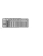
Mode
SP
SP
EP
EP
Video signal
Color bar
Monoscope
Color bar
Monoscope
Audio signal
(HiFi/Normal)
400 Hz
Time
Seven minutes
Three minutes
Seven minutes
Three minutes
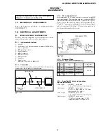
7-1. MECHANICAL ADJUSTMENTS
Refer to the SERVICE MANUAL of VHS MECHANICAL
ADJUSTMENT VI.
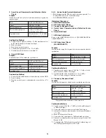
7-2. ELECTRICAL ADJUSTMENTS
2-1.
PRE-ADJUSTMENT PREPARATIONS
Necessary items and indications for total adjustment of electric
circuit of this machine will be described in this chapter.
2-1-1.
Instruments to be Used
1) Color TV
2) Oscilloscope 1 or 2 phenomena, band more than 30 MHz, delay
mode, as provided.
3) NTSC pattern generator
4) Digital voltmeter
5) Audio level meter
6) Audio noise meter
7) Audio generator
8) Attenuator
9) Alignment tape
Part Code: 8-192-605-32 KRV-51N2
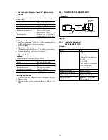
2-1-2.
Connection
Unless otherwise specified, connect and adjust the measuring
instruments as shown in the following diagram.
Fig. 7-2-1
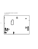
During the adjustment, see the Parts Arrangement
Diagram for Adjustments on Page 7-6.
Fig. 7-2-2
2-1-4.
Alingment Tapes
[Alignment Tape (KRV-51N2/KRV-51P)]
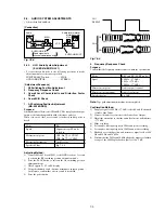
2-1-3.
Set-up of Adjustment
In this adjustment, NTSC pattern generator is connected with LINE
input signal terminal. When checking with tuner, connected AERIAL
terminal. Check that the amplitudes of video signal SYNC signal, of
picture portions, and of burst signals are flat at approximately 0.3,
0.7 and 0.3 V, respectively, and that the level ratio of the burst signal
and “red” signal are 0.30: 0.66. Fig. 7-2-2. shows video signals (color
bars) used in adjusting the video section.
NTSC
2-1-5.
Specified I/O Level and Impedance
Input/output terminal
Video inputs
LINE IN
: phono jack
1 Vp-p, 75
Ω
, unbalanced, sync negative
Audio inputs
LINE IN
: phono jacks
47 kW, –7.5 dBs (0 dBs = 0.775 Vrms)
More than 10 kW, –4 dBs
Video outputs
LINE OUT : phono jack
1 Vp-p, 75
Ω
, unbalanced, sync negative
Audio outputs
LINE OUT : phono jacks
–7.5 dBs at load impedance 47 k
Ω
Output impedance : less than 10
Ω
SLV-ED212/ED717/ED818/ED919/LF1
Video output
(75
Ω
)
Pattern generator
VCR
VIDEO LINE IN
Monitor TV
VIDEO LINE OUT
Содержание RMT-V310
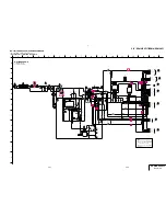
Страница 24: ...SLV ED212 ED717 ED818 ED919 LF1 3 1 3 2 SECTION 3 BLOCK DIAGRAMS 3 1 OVERALL BLOCK DIAGRAM ...
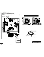
Страница 27: ...SLV ED212 ED717 ED818 ED919 LF1 3 4 AUDIO BLOCK DIAGRAM 3 7 3 8 ...
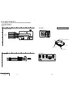
Страница 28: ...SLV ED212 ED717 ED818 ED919 LF1 3 5 TUNER BLOCK DIAGRAM 3 9 3 10 ...
Страница 29: ...SLV ED212 ED717 ED818 ED919 LF1 3 6 MODE CONTROL BLOCK DIAGRAM 3 11 3 12 ...
Страница 30: ...SLV ED212 ED717 ED818 ED919 LF1 3 7 POWER BLOCK DIAGRAM ED212 ED717 ED919KR LF1 ED818 ED919TW 3 13 3 14E ...


