


53
Additional Operations
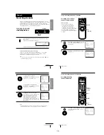
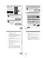
Operation
(when recording on this VCR)
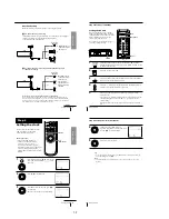
Before you start editing
• Turn on your TV and set it to the
video channel.
• (SLV-ED919KR/ED717KR)
Press INPUT SELECT or CH +/– to
display “L1” or “L2” in the display
window.
• (SLV-ED212KR)
Press INPUT SELECT or CH +/– to
display “L” in the display window.
• Press REC SPEED to select the tape
speed.
1
Insert a source tape with its safety tab removed into the other
(playback) VCR. Search for the point to start playback and set it to
playback pause.
2
Insert a tape with its safety tab in place into this (recording) VCR.
Search for the point to start recording and press
X
PAUSE.
3
Press
z
REC and set it to recording pause.
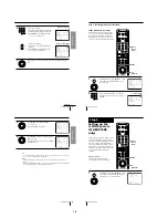
4
To start editing, press the
X
PAUSE buttons on both VCRs at the same
time.
To stop editing
Press the
x
STOP buttons on both VCRs.
Tips
• To edit more precisely, press the
X
PAUSE buttons on the VCRs to release pause.
• To cut out unwanted scenes while editing, press
X
PAUSE on this VCR when an
unwanted scene begins. When it ends, press
X
PAUSE again to resume recording.
Note
• If you start recording following the procedure above, the VCR won’t start recording
with the APC function. To record a tape with the APC function, press
z
REC again
during recording pause in step 3 so that the VCR analyzes the tape. Then when you
start recording in step 4, press
X
PAUSE immediately after the APC indicator stops
flashing. If you press
X
PAUSE before the APC indicator stops flashing, the APC
function is canceled.
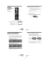
z
REC
X
PAUSE
Additional Information
54
Additional Information
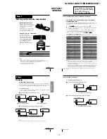
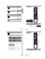
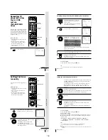
General setup information
Attaching the external
antenna connector
When using a 300-ohm twin lead cable
for VHF/UHF antenna, use an antenna
connector (not supplied) to connect the
antenna to the VCR.
1
Loosen the screws on the antenna connector.
2
Wind the twin leads around the screws on the antenna connector.
3
Retighten the screws.
Attaching a UHF/VHF band
mixer
When using both 75-ohm coaxial cable
and 300-ohm twin lead cable for VHF/
UHF antenna, use a UHF/VHF band
separator/mixer (not supplied) to
connect the antenna to the VCR.
1
Loosen the screws on the mixer.
2
Wind the twin leads around the screws on the mixer.
3
Retighten the screws.
4
Connect the 75-ohm coaxial cable to the mixer.
300-ohm twin
lead cable
UHF/VHF
band
separator/
mixer (not
supplied)
300-ohm twin
lead cable
75-ohm coaxial
cable
Antenna
connector (not
supplied)
59
Additional Information
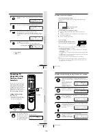
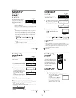
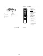
Index to parts and controls
Front panel
Refer to the pages indicated in parentheses ( ) for details.
1
?/1
POWER switch (36)
2
Tape compartment
3
A
EJECT button (23)
4
m
REW (rewind) button (23, 43)
5
H
PLAY button (23)
6
M
FF (fast-forward) button
(23, 43)
7
z
REC (record) button (25)
8
x
STOP button (23)
9
X
PAUSE button (23)
0
SEARCH MODE indicator (37, 38,
39, 41, 42)
qa
EASY TIMER knob (27, 37, 38, 39,
41, 42)
qs
CHANNEL/TR/–
buttons (25, 49)
qd
Remote sensor (5)
qf
REC SPEED SP (Standard Play)/EP
(Extended Play) button (28)
qg
INPUT SELECT button (26)
qh
ONE TOUCH TUNING button (13)
qj
R
2
(Reality Regenerator) button
(SLV-ED919KR and ED717KR only)
(49)
qk
LINE-2 IN VIDEO/AUDIO L/R
jacks (SLV-ED919KR and ED717KR
only) (52)
continued
!¶ !§
8
!¢
!∞
!º
1
3 4 5
2
6
7
9
!¡
!™
!£
!•
Additional Information
60
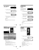
Index to parts and controls (continued)
Rear panel (SLV-ED919KR)
1
AC power cord
2
LINE-1 IN AUDIO R/L/VIDEO
jacks (7)
3
VHF/UHF IN connector (9)
4
VHF/UHF OUT connector (9)
5
RF (Radio Frequency) UNIT switch
(10)
6
LINE OUT AUDIO R/L/VIDEO
jacks (7)
1
AC power cord
2
LINE-1 IN AUDIO/VIDEO jacks
(52)
3
VHF/UHF IN connector (9)
4
VHF/UHF OUT connector (9)
5
RF (Radio Frequency) UNIT switch
(10)
6
LINE OUT AUDIO/VIDEO jacks
(8)
Rear panel (SLV-ED717KR and ED212KR)
2
1
3
6
54
2
1
3
54
6
1-13
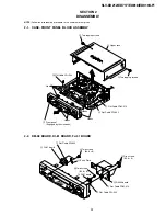
Содержание RMT-V310
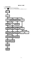
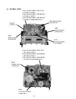
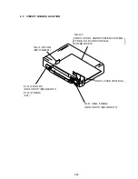
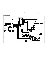
Страница 24: ...SLV ED212 ED717 ED818 ED919 LF1 3 1 3 2 SECTION 3 BLOCK DIAGRAMS 3 1 OVERALL BLOCK DIAGRAM ...
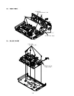
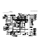
Страница 27: ...SLV ED212 ED717 ED818 ED919 LF1 3 4 AUDIO BLOCK DIAGRAM 3 7 3 8 ...
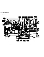
Страница 28: ...SLV ED212 ED717 ED818 ED919 LF1 3 5 TUNER BLOCK DIAGRAM 3 9 3 10 ...
Страница 29: ...SLV ED212 ED717 ED818 ED919 LF1 3 6 MODE CONTROL BLOCK DIAGRAM 3 11 3 12 ...
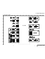
Страница 30: ...SLV ED212 ED717 ED818 ED919 LF1 3 7 POWER BLOCK DIAGRAM ED212 ED717 ED919KR LF1 ED818 ED919TW 3 13 3 14E ...


