


SLV-ED212/ED717/ED818/ED919/LF1
6-1E
SECTION 6
ERROR CODE
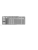
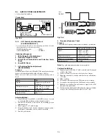
This set displays an error code, and a mode code in case of
error on the display tube, if the operation stopped by error.
The following provides description concerned.
A: Error code ....................................................... Table 6-1
B: Mode code in case of error ............................ Table 6-2
These codes are displayed at lower 5-digit positions of display
tube.
In this case, “ : ” between digits is not displayed.
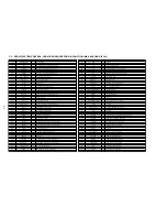
Table 6-1.
Error Codes
Table 6-2.
Mode Codes in Case of Error
Display tube (lower 5 digits)
A
B
Code
Description
0
NO ERROR
1
CAM ENCODER ERROR, LOAD DIRECTION
2
CAM ENCODER ERROR, UNLOAD DIRECTION
3
T REEL ERROR
4
S REEL ERROR
5
CAPSTAN ERROR
6
DRUM ERROR
7
INITIALIZE ERROR
8
CASSETTE UNLOADING ERROR
9
RESERVED
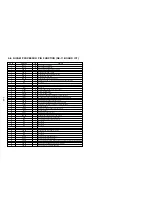
Code
Description
0
EJECT (POWER ON)
1
EJECT (POWER OFF)
2
UNLOAD STOP
3
STOP (POWER ON)
4
POWER OFF (CASSETTE IN)
5
F. FWD
6
REW
7
LOW SPEED F. FWD
8
LOW SPEED REW
9
STANDBY
10
REC
11
REC (VISS)
12
REC PAUSE
13
PLAY
14
A. DUB
15
A. DUB PAUSE
16
CUE
17
REV
18
STILL (MECHA FWD)
19
FWD FRAME BY FRAME (FWD SLOW)
20
STILL (MECHA RVS)
21
RVS FRAME BY FRAME (RVS SLOW)
Содержание RMT-V310
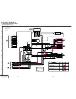
Страница 24: ...SLV ED212 ED717 ED818 ED919 LF1 3 1 3 2 SECTION 3 BLOCK DIAGRAMS 3 1 OVERALL BLOCK DIAGRAM ...
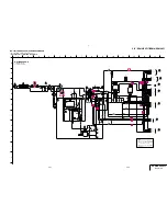
Страница 27: ...SLV ED212 ED717 ED818 ED919 LF1 3 4 AUDIO BLOCK DIAGRAM 3 7 3 8 ...
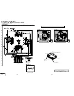
Страница 28: ...SLV ED212 ED717 ED818 ED919 LF1 3 5 TUNER BLOCK DIAGRAM 3 9 3 10 ...
Страница 29: ...SLV ED212 ED717 ED818 ED919 LF1 3 6 MODE CONTROL BLOCK DIAGRAM 3 11 3 12 ...
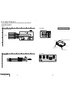
Страница 30: ...SLV ED212 ED717 ED818 ED919 LF1 3 7 POWER BLOCK DIAGRAM ED212 ED717 ED919KR LF1 ED818 ED919TW 3 13 3 14E ...


