


– 4 –
SERVICE NOTE
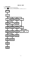
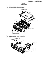
1. DISASSEMBLY
• This set can be disassembled in the order shown below.
Note:
Pages in indicated pages in the SERVICE MANUAL.
Pages in indicated pages in the VHS MECHANICAL ADJUSTMENT MANUAL VI.
Set
Upper case
(Page 2-1)
Front Panel
Section
(Page 2-1)
Pinch Press
Block Ass’y
(Page 14)
Ground Shaft
Ass’y
(Page 13)
Mechanism
Deck
(Page 2-3)
FL Complete
Ass’y
(Page 13)
Drum
Ass’y
(Page 13)
Rear
Panel
(Page 2-2)
Rubber
Belt
(Page 15)
Rubber
Belt
(Page 15)
Slider
(Page 26)
Loading
Gear (T, S)
(Page 28)
Retainer
Plate
(Page 22)
Rubber
Belt
(Page 15)
Capstan
Motor
(Page 15)
FL Slider
Block Ass’y
(Page 22)
Pully Gear
Ass’y
(Page 29)
Cam Motor
Retainer
(Page 31)
Cam Gear
(Page 23)
Cam Motor
(Page 31)
Reel Direct
Ass’y
(Page 30)
MA-402
Board
(Page 2-2)
Rotary
Switch
(Page 2-3)
Tuner
Unit
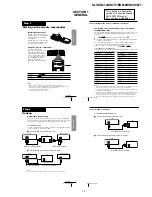
Содержание RMT-V310
Страница 24: ...SLV ED212 ED717 ED818 ED919 LF1 3 1 3 2 SECTION 3 BLOCK DIAGRAMS 3 1 OVERALL BLOCK DIAGRAM ...
Страница 27: ...SLV ED212 ED717 ED818 ED919 LF1 3 4 AUDIO BLOCK DIAGRAM 3 7 3 8 ...
Страница 28: ...SLV ED212 ED717 ED818 ED919 LF1 3 5 TUNER BLOCK DIAGRAM 3 9 3 10 ...
Страница 29: ...SLV ED212 ED717 ED818 ED919 LF1 3 6 MODE CONTROL BLOCK DIAGRAM 3 11 3 12 ...
Страница 30: ...SLV ED212 ED717 ED818 ED919 LF1 3 7 POWER BLOCK DIAGRAM ED212 ED717 ED919KR LF1 ED818 ED919TW 3 13 3 14E ...


