7(E)
6
Camera number/tally indication window
The number of the camera being controlled from this
panel is displayed in orange.
When a red tally signal is sent to the camera, the
number is displayed in black and the background of
the number lights in red.
When a green tally signal is sent to the camera, the
number is displayed in black and the background of
the number lights in green.
When both the red and green tally signals are
simultaneously sent, the left half of the background
lights in red and the right half lights in green.
7
ALARM indicator
Lights when trouble occurs in the camera system and
the self-diagnostic function activates at the video
camera or the CCU/HDCU-series.
8
CALL button
Press to send a call signal to the video camera, on
which the CALL button lights. The tally lamps on the
camera and the red tally lamp on the CCU/HDCU-
series light when not lit, or go dark when lit.
When the CALL button on the video camera is
pressed, the CALL button on this panel lights and a
buzzer sounds.
9
PANEL ACTIVE button
Press and light up the button to permit this panel to
control the camera system (Panel active status).
The IRIS/MB ACTIVE button also lights.
If you press this button so that it goes dark, the panel
will be locked, preventing accidental misoperation.
0
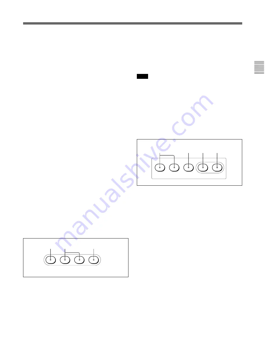
Power and output signal select block
A
CAM PW (camera power) button
Press and light up this button to turn the power supply
to the video camera ON. (The button promptly flashes
until the camera becomes ready for transmission.)
When you press this button again, it starts flashing and
the power supply is turned off.
B
Signal output select buttons
Press and light up one of these buttons to activate the
test signal generator of the video camera and send the
respective signals.
TEST: To send a signal to test the video circuits
BARS: To send a color bar signal
Note
The BARS button takes priority to the TEST button. If
the BARS button is lit, press the button to turn it dark
before pressing the TEST button.
C
CLOSE button
Press and light the button to close the iris. To release
the close mode, press the button again so that it goes
dark.
qa
AUTO SETUP block
A
Auto adjustment item select buttons
Press and light up these buttons to select the items to
be automatically adjusted.
SKIN DTL AUTO HUE: Skin tone detail automatic
hue
LEVEL: Gamma balance, knee point, master black
level, etc.
B
START/BREAK button
Press to start automatic adjustment of the selected
items.
The button lights during adjustment and goes dark
when adjustment is completed. If you press the button
when lit, the automatic adjustment is canceled and the
button flashes. To stop the flashing, press the button
again.
C
WHITE (white balance) button
Press to automatically adjust the white balance.
The button lights during adjustment and goes dark
when adjustment is completed.
If you press this button when lit or the START/
BREAK button, the automatic adjustment is canceled
and the button flashes. To stop the flashing, press the
button again.
CAM PW
TEST
BARS
CLOSE
A
B
C
LEVEL
AUTO SETUP
SKIN DTL
AUTO HUE
START/
BREAK
WHITE
BLACK
A
B
D
C
Содержание RCP-750
Страница 43: ......
Страница 75: ...Printed in Japan Sony Corporation ...
Страница 88: ...12 E Mounting on a Console The RCP 750 751 can be mounted on a console as shown below ...
Страница 108: ...RCP 750 751 SY 3 206 914 05 1 Printed in Belgium 2008 06 08 2002 Sony Corporation 3 2 0 6 9 1 4 0 5 1 ...
Страница 146: ...Specifications 77 ...
Страница 147: ...Specifications 78 ...
Страница 149: ...Sony Corporation RCP 920 SY RCP 921 SY 3 096 914 03 1 Printed in Belgium 2008 06 08 2006 3 0 9 6 9 1 4 0 3 ...


