Initial Settings
67
2
Turn the right adjustment knob to change the
setting, and press ENTER button.
The shutter display setting is changed.
4
Press CLEAR button.
The first screen of the RCP configuration menu
reappears.
The SHUTTER display on the SHUTTER page of the
paint menu will be displayed as an angle (degree
units).
To change the RCP number
When using the RCP-920/921 in a multi-camera network
system, you must assign the unit a unique device number.
When connecting the unit to a CCU directly or connecting
the unit to a CNU, this configuration is not necessary.
Note
Malfunctions may occur if you assign the RCP a number
that is already in use by another device in a multi-camera
system connected via Ethernet. Be sure to assign a
different number for each device.
1
Move the cursor to SETTING in the RCP
configuration menu, and press ENTER button.
The settings and adjustment screens appear.
2
Use the
v
and
V
buttons to move through the settings
and adjustment screens, and display the <RCP No.
SET> page.
3
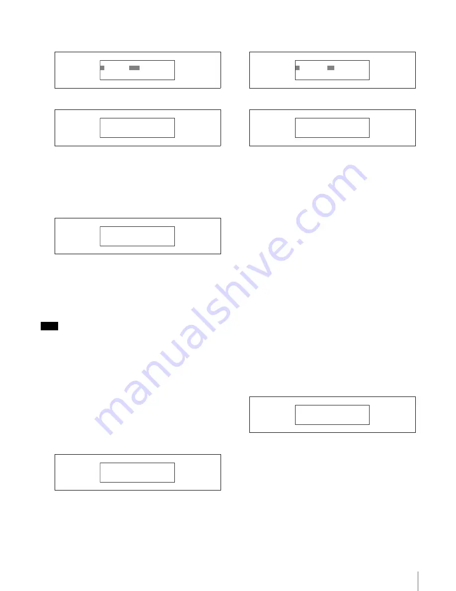
Change the RCP number setting.
1
Press ENTER button to enable configuration.
The cursor appears as “?” and the setting flashes.
2
Turn the right adjustment knob to change the
setting, and press ENTER button.
The RCP number setting is changed.
4
Press CLEAR button.
The first screen of the RCP configuration menu
reappears.
To change the output destination for
previews (RCP-920)
When you press the IRIS control lever/preview switch on
the RCP-920, preview key signals are output. You can
enable or disable the output settings for destinations
individually.
The output destinations you can configure are as follows.
• EXT I/O connector on the RCP unit (Factory setting:
ON)
• External output connector on the CCU (Factory setting:
OFF)
• S-BUS system via the CNU (Factory setting: OFF)
1
Move the cursor to SETTING in the RCP
configuration menu, and press ENTER button.
The settings and adjustment screens appear.
2
Use the
v
and
V
buttons to move through the settings
and adjustment screens, and display the <PREVIEW>
page.
3
Turn the right adjustment knob to move the cursor to
the preview output destination you want to configure.
To configure the EXT I/O connector on the RCP unit,
move the cursor to CONTACT.
4
Change the preview output setting.
1
Press ENTER button to enable configuration.
The cursor appears as “?” and the setting flashes.
ᴹᵐᵥᵲᵱᵱᵢᵯǽᵁᵦᵰᵭᵩᵞᵶᴻ
ᴼ
ᴾᵫᵤᵩᵢᴷǽǽ
ᵌᵋ
ᴹᵐᵥᵲᵱᵱᵢᵯǽᵁᵦᵰᵭᵩᵞᵶᴻ
ᴻᴾᵫᵤᵩᵢᴷǽǽᵌᵋ
ǽᵐᵅᵒᵑᵑᵂᵏǽǽǽǽǽǽǽǽǽᴮ ¯ ᴵ
ǽǽǽǽǽǽǽǽǽǽᵐᵅᵒᵑᵑᵂᵏᴷᵌᵋ
ǽᵊᵬᵡᵢ
ǽᵐᵅᵒᵑᵑᵂᵏǽǽǽǽǽǽǽǽǽǽᴮᴳ
ᴹᵏᵀᵍǽᵋᵬᴫᵐᵂᵑᴻ
ᴻᵏᵀᵍǽᵋᵬᴫᴷǽᴮ
ᴹᵏᵀᵍǽᵋᵬᴫᵐᵂᵑᴻ
ᴼ
ᵏᵀᵍǽᵋᵬᴫᴷǽ
ᴱ
ᴹᵏᵀᵍǽᵋᵬᴫᵐᵂᵑᴻ
ᴻᵏᵀᵍǽᵋᵬᴫᴷǽᴱ
ᴹᵍᵏᵂᵓᵆᵂᵔᴻ
ᴻᵀᵌᵋᵑᴾᵀᵑᴷǽǽǽǽǽǽǽǽǽᵌᵋ
ǽᵀᵀᵒᴷǽǽǽǽǽǽǽǽǽǽǽǽᵌᵃᵃ
ǽᵐᴪᴿᵒᵐᴷǽǽǽǽǽǽǽǽǽǽᵌᵃᵃ
Содержание RCP-750
Страница 43: ......
Страница 75: ...Printed in Japan Sony Corporation ...
Страница 88: ...12 E Mounting on a Console The RCP 750 751 can be mounted on a console as shown below ...
Страница 108: ...RCP 750 751 SY 3 206 914 05 1 Printed in Belgium 2008 06 08 2002 Sony Corporation 3 2 0 6 9 1 4 0 5 1 ...
Страница 146: ...Specifications 77 ...
Страница 147: ...Specifications 78 ...
Страница 149: ...Sony Corporation RCP 920 SY RCP 921 SY 3 096 914 03 1 Printed in Belgium 2008 06 08 2006 3 0 9 6 9 1 4 0 3 ...


