000
1. Overview: Name and Function of Parts
10
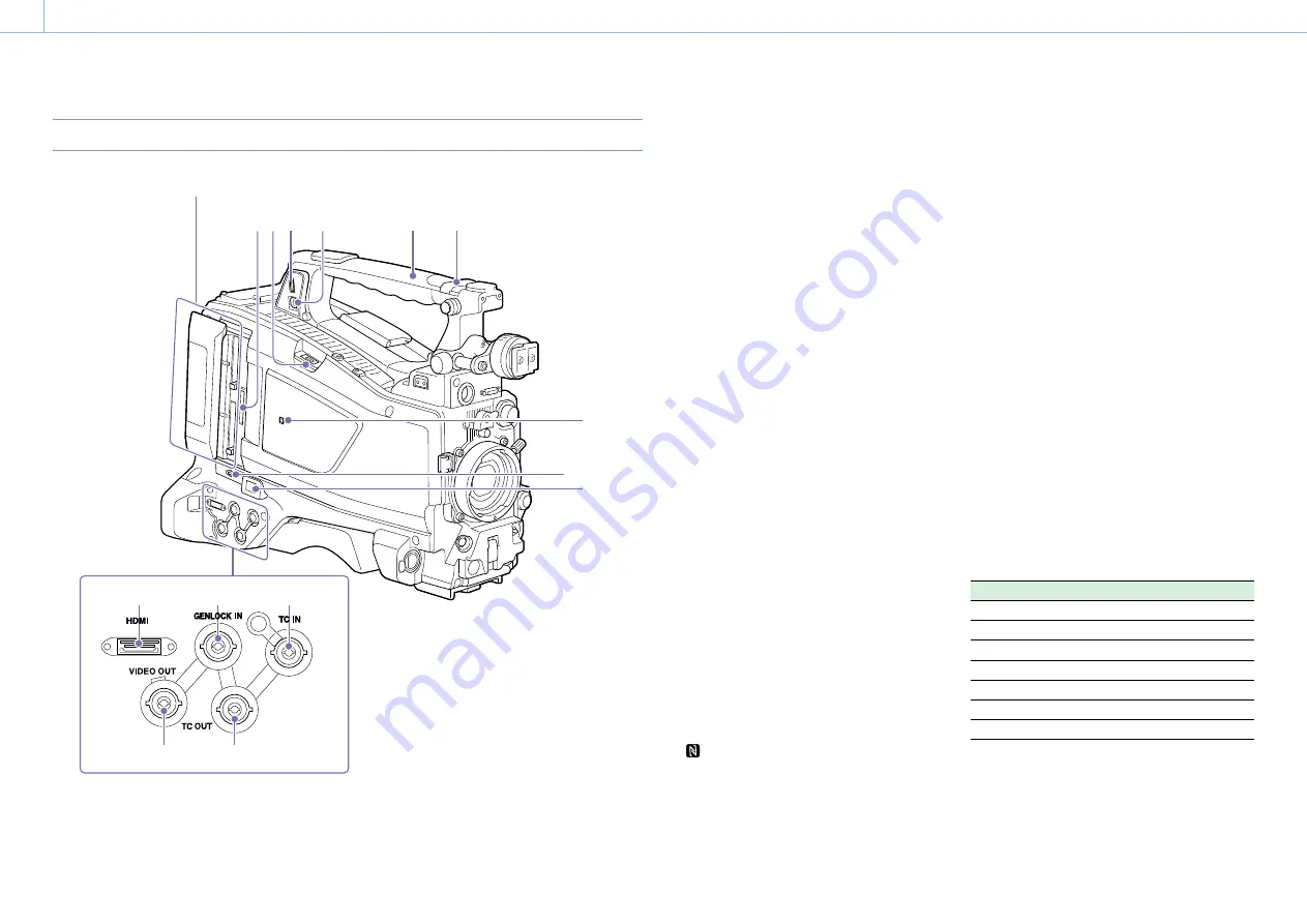
Handle and Memory Card Slot Side
1
7
2
3
9
8
4
5
6
10
13
14
11
12
SxS memory card slots (page 27)
1.
ASSIGNABLE 4/5 switches
You can assign a function using Operation
>Assignable Switch in the setup menu
(page 113).
Off is assigned to these switches when the
camcorder is shipped from the factory.
2.
GPS module
Contains a built-in GPS module.
“Obtaining Location Information (GPS)” (page 56)
[Note]
Do not grasp this part of the camcorder when the GPS
function is in use.
3.
PC connector
Used to put this camcorder into USB connection
mode and use it as an external storage device
for a computer. When a computer is connected
to this connector, every memory card inserted
in the camcorder is recognized as a drive on the
computer.
4.
External device connector
Connect to a PSZ-HA50 Portable Storage HDD
(option), PSZ-SA25 Portable Storage SSD (option),
a general-purpose external USB HDD, or USB flash
drive to copy clips from the recording media
inserted in an SxS card slot of the camcorder to
USB media.
[Note]
This connector should be used only for connecting the type
of devices above. It cannot be used for connecting a USB
hub or other devices.
5.
USB wireless LAN module connector
Connect to an IFU-WLM3 USB Wireless LAN
Module (supplied), CBK-WA02 Wireless LAN
Adaptor (option), or combination of CBK-NA1
Network Adaptor Kit (option) and modem (option)
to enable communications with wireless LAN
devices and networks.
“Connecting Devices using Wireless LAN” (page 58)
“Connecting to the Internet” (page 62)
6.
Insert an SD card for recording proxy data.
7.
(NFC) mark
A built-in NFC antenna is provided.
8.
SLOT SELECT (SxS memory card select)
button
When SxS memory cards are loaded in both card
slots A and B, press this button to select the card
you want to use (page 27).
9.
Network connector
Connects to a network via a wired LAN connection
using a LAN cable (sold separately).
[CAUTION]
ˎ
ˎ
For safety, do not connect the connector for peripheral
device wiring that might have excessive voltage to this
port.
Follow the instructions for this port.
ˎ
ˎ
When you connect the LAN cable of the unit to peripheral
device, use a shielded-type cable to prevent malfunction
due to radiation noise.
“Connecting to the Internet” (page 62)
10.
HDMI connector
Connect an HDMI device, such as a monitor or
recording unit, to output HD or SD HDMI video
and audio signals.
[Note]
4K (QFHD) output is not supported.
11.
GENLOCK IN (genlock signal input)
connector (BNC type)
This connector inputs a reference signal when the
camcorder is to be genlocked or when timecode
is to be synchronized with external equipment.
The supported reference signals vary depending
on the current system frequency as shown in the
following table.
System frequency Supported reference signals
59.94i
1080/59.94i, 480/59.94i
59.94P
1080/59.94i, 480/59.94i
50i
1080/50i, 576/50i
50P
1080/50i, 576/50i
29.97P
1080/59.94i, 480/59.94i
25P
1080/50i, 576/50i
23.98P
1080/23.98PsF
12.
TC IN (timecode input) connector (BNC type)
To apply an external lock to the timecode of the
camcorder, input the reference timecode.
“Setting the Timecode” (page 43)
13.
VIDEO OUT connector (BNC type)
Outputs video signals for monitoring.


