66
28. Grand Wega Video Process
Table 28-1 - Video Circuit Board Inputs / Outputs
Board
Input(s)
Board Function
Output(s)
U
•
TV Tuner, S Video
•
Composite Video
•
Component video inputs.
•
NTSC Input switching
•
Component video pass-
through.
•
TV Output to rear panel,
•
Composite S video to BC4
bd.
•
Component video to BC Bd.
A
•
VHF antenna
•
TV tuner and control
•
Interconnecting video boards
Various
BC4
•
Composite Video (V) or
S video (Y & C)
Comb filter separates the Y & C
from the composite V (video)
signal.
•
Separate Y & C Outputs for
the BC Bd.
BC
•
S Video (Y & C)
•
Component video inputs.
•
Creates a Main and Sub
picture video path
•
Channels video into the Main
(DRC) & Sub picture video
paths.
•
Main picture component
video
•
Sub picture component
video
BB
•
Main picture component
video
•
Sub picture component
video
•
Switches picture location
when NTSC video is input.
•
Adds User Menu into the
video path.
•
RGB and Sync Output to
the (LCD) light box
assembly.
C
•
RGB and Sync input
Independent RGB processing
into separate RGB LCD panels.
•
Display outputs onto mirror.
Troubleshooting
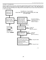
Video symptoms can be classified into three groups:
•
White Screen – Video path open on any video signal board.
•
Black Screen - BB board or optical unit are suspect.
•
Video Screen Distortion – Narrow down by checking the features.
In a conventional TV, a loss of video signal results in a white screen with normal TV sound. This is also true in
this LCD projection TV. However, if the screen is dark with normal sound, either the LCD optical unit or the
previous BB circuit board may be bad.
On the other hand, a dark screen without sound indicates both video and audio muting and not a problem in the
video chain. Muting is caused by: 1) the Main Micro because of: a communications problem with another IC; 2)
a fan defect; 3) a lamp circuit defect; or 4) an audio output failure, which will also cause TV shutdown. Muting the
A/V is not a video failure. A video failure does not affect the sound.
White Screen
If the screen is white, there may be no input to the light box. Press the Menu button. If an OSD menu appears,
the optical unit is good and the previous stages are bad (BC or BB board). If no OSD, use Table 28-2 and a DVM
to verify these inputs to the optical unit before changing it. Measure the input voltage at CN5002 and verify RGB
input signal at CN5005. If the input voltages and signals are both present, the optical unit is suspect.


