background image

Selecting the Gamma

69

Chap

ter
 3

  Ba
s

ic

 Ad

jus
tme
nt

s

 an
d Set

tings

Notes

• When the camera is in Custom mode, white clip 

level adjustment is allowed, but the white limit 
values shown in the “Available Hyper Gamma 
choices” table may not be obtained if you adjust 
the white clip level.

• With a Hyper Gamma selected, the knee and 

gamma level adjustments are not allowed, even in 
Custom mode.

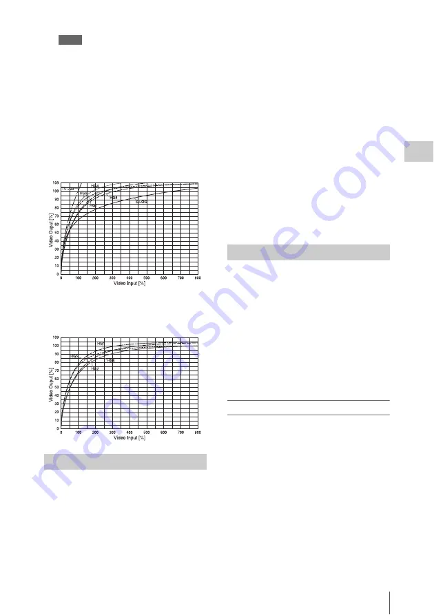
HyperGamma curves

When SPECIAL is selected on the first line of 
TABLE on the <GAMMA> page (with the 
optional HKSR-9003 installed), the 
second line indicates S-LOG (Sony Log).
Sony Log (called “S-Log” below) is a gamma 
function optimized for CCD cameras. It was 
developed for use in the DI (digital intermediate) 
workflow of film production, in which the camera 

negative captured on film is digitally processed to 
create the digital master release print. 
S-Log allows you to allows you to monitor the 
full latitude of Sony digital cinema cameras, 
which is comparable to that of film cameras, and 
to perform color correction (grading). The camera 
image can be treated as a “digital negative” in 
workflows optimized for digital processing of 
negative film.
By working with this “digital negative”, you can 
make a smooth transition from film production to 
digital cinema production. You can use the same 
ISO sensitivity ratings, light meters, and shooting 
style as always, and enjoy a latitude comparable 
to that of negative film.

For more information about S-Log, refer to the “S-
Log Whitepaper.” Contact a Sony service 
representative for information about how to obtain 
this whitepaper.

You can also use the Sony CvpFileEditor

 1)


software to create your own gamma tables on 
your personal computer, and load those table into 
the unit via a “Memory Stick”.
Note that gamma control (LEVEL, ON/OFF) 
may be disabled when a user gamma table is 
selected, because the gamma may have been 
forcibly fixed when the table was created. 
When the unit is shipped from the factory, it is set 
up to use a user gamma table initialized to 
HG8009G33.

1) CvpFileEditor is a trademark of Sony Corporation.

To select a user gamma table

1

To use a gamma table you have created, 
load it into the unit.

Load the gamma table data via a “Memory 
Stick” using the <USER GAMMA> page of 
the FILE menu in Custom mode.

Using S-LOG

HG3: HG3259G40
HG4: HG4609G33
HG7: HG8009G40
HG8: HG8009G33

HG1: HG3250G36
HG2: HG4600G30
HG5: HG8000G36
HG6: HG8000G30

Using User Gamma

Содержание HKSR-9003

Страница 1: ...on recycled paper SRW 9000 SY 4 160 062 01 1 Printed in Japan 2009 09 08 2009 HD CAMCORDER SRW 9000 HD SDI EXPANSION BOARD HKSR 9001 RGB 4 4 4PROCESSOR BOARD HKSR 9003 OPERATION MANUAL English 1st Edition HD CAMCORDER SRW 9000 ...

Страница 2: ...ty to operate this equipment All interface cables used to connect peripherals must be shielded in order to comply with the limits for a digital device pursuant to Subpart B of Part 15 of FCC Rules This device complies with Part 15 of the FCC Rules Operation is subject to the following two conditions 1 this device may not cause harmful interference and 2 this device must accept any interference rec...

Страница 3: ...nde udstyr SRW 9000 overholder de væsentlige krav og øvrige relevante krav i direktiv 1999 5 EF For yderligere information gå ind på følgende hjemmeside http www compliance sony de Sony Corporation vakuuttaa täten että SRW 9000 tyyppinen laite on direktiivin 1999 5 EY oleellisten vaatimusten ja sitä koskevien direktiivin muiden ehtojen mukainen Halutessasi lisätietoja käy osoitteessa http www comp...

Страница 4: ... écouteurs ou du casque peut provoquer une baisse de l acuité auditive Pour utiliser ce produit en toute sécurité évitez l écoute prolongée à des pressions sonores excessives Pour les clients au Canada Cet appareil numérique de la classe B est conforme à la norme NMB 003 du Canada Pour les clients en Europe Ce produit portant la marque CE est conforme à la Directive sur la compatibilité électromag...

Страница 5: ...egeln Für Kunden in Europa Dieses Produkt besitzt die CE Kennzeichnung und erfüllt die EMV Richtlinie der EG Kommission Angewandte Normen EN55103 1 Elektromagnetische Verträglichkeit Störaussendung EN55103 2 Elektromagnetische Verträglichkeit Störfestigkeit Für die folgenden elektromagnetischen Umgebungen E1 Wohnbereich E2 kommerzieller und in beschränktem Maße industrieller Bereich E3 Stadtbereic...

Страница 6: ...apter 2 Preparations Connecting a Power Supply 27 Using a Battery Pack 27 Using AC Power 28 Turning on the Power 28 Checking the Power and Voltage 28 Mounting the Lens 29 Attaching the Viewfinder 31 Connecting Audio Input 32 Using a Microphone 32 Connecting Line Input Audio Equipment 32 Connecting an Audio Multiplexer MUX to the AUX IN Connector When Using the HKSR 9001 33 Mounting on a Tripod 34 ...

Страница 7: ...e Brightness of the Subdisplay 49 Selecting Gamma Tables 49 Selecting Pages to Display in the Subdisplay 50 Adjusting the Black Balance 51 Adjusting the White Balance in Custom Mode 51 Setting the Camera Outputs 53 Selecting Video Output Signals for the Connectors 53 Setting the Monitor Picture 53 Outputting Color Bars 56 Viewing Settings and Indications in the Viewfinder 57 Viewing the Basic Stat...

Страница 8: ...ing 77 Making Audio Signal Settings 77 Setting Recording Audio Levels 78 Making Timecode and User Bits Settings 79 Shooting 82 Continuous Recording 83 Playback Checking the Recording 84 Preparing for Playback 84 Checking the Last Three Seconds of the Recording Recording Review 86 Checking the Recording on a Color Video Monitor Playback in Color 86 Checking the Camera Picture on the Viewfinder and ...

Страница 9: ... File Operations 146 Using a Memory Stick 146 Storage and Retrieval of the Operator File 147 Registration and Retrieval of Lens Files 147 Storage and Retrieval of the Scene Files 148 Storage and Retrieval of Reference Files 149 Reading User Gamma Curves 150 Storing OHB Files 150 Resetting to the Initial Settings 151 Appendixes Using the RM B750 153 Connection 153 Operating the Camera Menu 153 Moni...

Страница 10: ...spections 162 Head Cleaning 162 Condensation 162 Note About the Battery Terminal 163 About Recording Playback Formats 164 What Is Dual Link 166 MPEG 4 VISUAL PATENT PORTFOLIO LICENSE 167 Specifications 167 Lip Sync Compensation 170 Index 171 ...

Страница 11: ...nit supports a variety of 1080 formats for the production of high end content such as movies commercials and broadcast programming 1080 1920 progressive formats 23 98PsF 24PsF 25PsF 29 97PsF 50P 59 94P 1080 1920 interlaced formats 50i 59 94i RGB 4 4 4 shooting and recording Because of its high compatibility with computer graphics and digital compositing systems the RGB 4 4 4 format opens up a wide...

Страница 12: ...io input Addition of the optional HKSR 9001 HD SDI Expansion Board makes dual link output available RGB 4 4 4 and 1080 30PsF or YCbCr 4 2 2 and 1080 60P With this optional board installed you can also input 12 channels of audio Shutter control When adjusting the electronic shutter you can display shutter settings as shutter angles in degrees or shutter speeds in seconds Image inversion function Th...

Страница 13: ...ion Name Model name HD Electronic Viewfinder HDVF 20A C30WR Name purpose Magnification Part No Fog proof filter 1 547 341 11 Eyepiece high magnification 2 8D to 2 0D A 8262 537 A Riser plate Control panel Main unit AP 1 Assistant Panel optional V shoe plate Eyepiece low magnification 3 6D to 0 8D A 8262 538 A Eyepiece aberration compensation 3 6D to 0 4D A 8267 737 A Eyepiece 3 magnification 2 4D ...

Страница 14: ... see Attaching the Viewfinder page 31 c Filter selector The selector knobs switch between the unit s built in filters Name Model name Remote Control Unit RM B750 B150 Purpose Name HD video output monitoring HDSDI HD video monitor SD Video Output monitoring TEST OUT SD video monitor Audio monitoring EARPHONES Stereo headphones Name purpose Model name HDSDI portable recorder player nanoFlash Converg...

Страница 15: ...fitted for protection from dust For details see Mounting the Lens page 29 a Cassette insertion slot Insert cassettes For details see Loading and Unloading Cassettes page 76 b CTRL VTR control panel connector Connect the cable of the supplied control panel A short cable is connected when the unit is shipped from the factory You can exchange the short cable for the supplied extension cable For detai...

Страница 16: ...nals in the Camera menu see page 53 The same signals are output from the HD SDI MON2 connector on the rear panel i EXT I O external control connector 5 pin Use the connector for control via RS 232C a Assignable buttons 5 to 8 You can assign frequently used functions to these buttons by menu settings The following functions are assigned when the unit is shipped from the factory For details see Assi...

Страница 17: ...e panel h Riser plate focus reference mark φ This is a plate for attaching movie accessories It has a mark to show the focus standard position A wrench 2 5 mm for use in attaching and detaching the viewfinder is stored inside When you want to use a tripod with the optional VCT 14 Tripod Attachment exchange the riser plate for the supplied V shoe plate See To use the optional VCT 14 Tripod Attachme...

Страница 18: ... indicator flashes c GENLOCK IN external sync signal input connector BNC type Used for input of an external genlock signal HD tri sync d TC IN timecode input connector BNC type Connect to the timecode output connector of a timecode generator VTR or other external device Use this connector when you want to lock the internal timecode generator to external timecode e TC OUT timecode output connector ...

Страница 19: ... m HD SDI MON2 HDSDI monitor output 2 connector BNC type Use in the same way as the HD SDI MON1 connector on the left side panel see page 16 a Lock release button When removing the control panel use this button For details see Attaching the Control Panel page 35 b Handle Use to carry the unit You can attach an accessory to the seven screw holes 3 8 4 1 4 3 on the top of the handle You can also att...

Страница 20: ...KEY INHI item see page 137 in the SYSTEM Setup menu is set to ALL setting this switch to ON disables operation buttons to prevent misoperations due to accidental button operations ON All operation buttons are disabled OFF During recording only the STOP button and PAUSE button are enabled All buttons are enabled when the system is not recording When the KEY INHI item in the SYSTEM Setup menu is set...

Страница 21: ... of the buttons change when they are pressed together with the FUNC button Name Pressed alone Pressed with FUNC button STOP button Stops tape transport Pressing this button while in standby on mode resets the still timer see page 138 Pressing the button while in standby off mode puts the unit into standby on mode Puts the unit into standby off mode ...

Страница 22: ...Once playback starts the search continues until the recording end point is found For details see Continuous recording in other cases page 83 Pressed with recording paused Plays back the most recently recorded material and then returns to recording pause mode recording review When SYSTEM SERVO REC REVIEW in the VTR menu is set to NORM factory default setting one press of this button rewinds the tap...

Страница 23: ...t recent search was interrupted Executes reverse direction searches With each press the search speed changes in the order 2 t 5 t 8 t 2 normal speed If a search is interrupted by another operation the next search is performed at the speed in effect at the time of the interruption Note When you are using the unit at the 880 Mbps recording rate 8 normal speed search is disabled For details on record...

Страница 24: ...displayed LTC VITC When timecode is being displayed whether it is LTC or VITC 1 INTRP Indicates that timecode could not be read accurately and has been interpolated DF NDF Whether the system is in DF drop frame or NDF non drop frame mode EXT LK Timecode is locked to external timecode KEY INHI The KEY INHI switch is set to ON REC INHI The cassette is record inhibited SRW 9000 Model name display 1 2...

Страница 25: ...on During recording RF appears and a green bar or a red bar lights to indicate the recording signal condition Normally the green bar lights If a recording problem occurs the red bar lights Green bar Recording signal quality is good Red bar Recording signal quality is degraded If this continues head cleaning or internal inspection is needed g Remaining tape time Displays the time remaining on the t...

Страница 26: ...l is shown on the subdisplay register the setting before disconnecting or connecting the cable 1 Connection cable 2 LOCK switch page 16 3 VF MENU DISPLAY button page 17 4 Assignable switches 1 to 3 page 17 5 CANCEL STATUS button page 17 6 RUN button and indicator page 17 7 Assignable 4 AUTO BLK BAL switch page 17 8 PAGE button page 18 9 SET button page 18 q Subdisplay page 17 qa MENU SEL ENTER dia...

Страница 27: ...peration manual The battery pack may not be recharged fully if you charge it immediately after use while it is still warm Remove the battery pack if the unit will be out of use for an extended period WARNING Batteries shall not be exposed to excessive heat such as sunshine fire or the like To attach the battery pack 1 Press the battery pack against the back of the unit aligning the line on the sid...

Страница 28: ... To check the type of power being used A battery mark appears in the lower left of the control panel display when power is being supplied from the battery attachment section A power plug mark appears when an AC adaptor is selected as the power supply Note that this mark does not reflect the actual type of power being used but reflects the settings of the following VTR menu items SYSTEM Setup BATTE...

Страница 29: ...conforms to the B4 2 3 lens mount For details on handling the lens refer to the operation manual for the lens 1 Push the lens mount lever up and remove the lens mount cap from the lens mount 2 Align the center pin on the lens with the notch in the lens mount and insert the lens into the mount Mounting the Lens Lens mount lever 60 oo 5 6 8 11 16 CL 2 8 2 1 6 T ff 4 30 20 15 12 10 8 7 6 5 6 5 Notch ...

Страница 30: ...e focal length 1 is necessary in the following situations When you attach a lens for the first time When you exchange lenses When during zooming the focus is not sharp in both telephoto and wide angle mode 1 Flange focal length The distance between the lens mount attachment plane and the imaging plan Note The positions of the controls for adjusting the flange focal length vary somewhat from lens t...

Страница 31: ...s To attach it at a lower position use the 2 5 mm wrench to loosen the three screws that secure the viewfinder plate remove the viewfinder plate and attach the viewfinder directly 2 Fit the viewfinder to the viewfinder shoe and slide the viewfinder horizontally The viewfinder stopper slides down automatically 3 Set the viewfinder to the most convenient position tighten the viewfinder positioning r...

Страница 32: ...hone to the microphone holder refer to the operation manual for the microphone Notes If the input level on this unit is not at an appropriate setting for the microphone sensitivity loud sounds may be distorted and the signal to noise ratio may be affected The AUDIO IN CH 1 and CH 2 connectors are female XLR connectors 3 pin to enable them to provide a phantom 48 V power supply If the microphone ca...

Страница 33: ... INTERNAL or GENLOCK IN To use the HD SDI OUT A connector Set GL MODE on the Genlock page To use the HD SDI MON1 2 connectors Set GL MODE on the Genlock page Multiplexing into external HDSDI signals Set REFERENCE on the GENLOCK page of the Camera MAINTENANCE menu to AUX IN Connecting an Audio Multiplexer MUX to the AUX IN Connector When Using the HKSR 9001 1 To AUDIO IN CH 1 or CH 2 connector 2 Au...

Страница 34: ...l over Check that the size of the selected hole matches that of the screw of the tripod If they do not match the unit cannot be attached to the tripod securely To use the optional VCT 14 Tripod Attachment Remove the riser plate and use the supplied six screws to attach the supplied V shoe plate in the position indicated in the figure HDSDI input HDSDI output Audio input a 75Ω coaxial cable a HDSDI...

Страница 35: ... top panel of the unit To detach the control panel Hold down the lock release button and detach the control panel by sliding it out To use the extension cable 1 Insert the belt bracket into hole A or B of the cable holder supplied 2 Detach the control panel 3 Remove the two cable holder attachment screws 4 Attach the cable holder using the attachment screws removed in step 2 Attaching the Control ...

Страница 36: ...lder of the AP 1 Assistant Panel When you are using the optional AP 1 Assistant Panel you can attach a cable holder to the AP 1 attachment hook base and use the cable holder to store the cable of the control panel See Attaching the AP 1 Assistant Panel Optional page 37 for more information about attaching the AP 1 Holder attachment screws Cable holder 1 Release the buckle of the holder 2 bundle th...

Страница 37: ...er attachment screws and use the screws to attach the hook base 2 Screw the cable holder into the hook base See To use the extension cable page 35 for more information about how to use the cable holder 3 Hang the reverse side of the AP 1 on the hook base 4 Connect the cable of the AP 1 to the CTRL VTR connector gather up the excess length of the cable and store it in the cable holder Attaching the...

Страница 38: ...r right corner of the screen 3 Turn the MENU SEL ENTER dial to move the pointer to TOP and press the MENU SEL ENTER dial The TOP MENU screen appears 4 Turn the MENU SEL ENTER dial to move the pointer to MAINTENANCE and press the dial The CONTENTS page of the MAINTENANCE menu appears The following display examples show Custom mode menus They include some items that do not appear in Cine mode 5 Turn...

Страница 39: ...d from or written to Memory Stick media is the operator file in the USER menu and the only file data that can be reset to factory defaults is the data in that file The only operation that can be carried out with lens files is loading a lens file by specifying its number The reference file items are fixed to the default values set at the factory even if you have changed the values in Custom mode Cu...

Страница 40: ...or subdisplay operations Right side of the unit Note When you turn the dial stop it at a position where you feel a click If you force the dial to stop at a non click position the operating stability of the dial on the AP 1 side may be affected Basic Settings with the Subdisplay Basic Operations in the Subdisplay VF MENU DISPLAY button confirm a setting PAGE button advance to the next page or confi...

Страница 41: ... setting items pressing the SET button moves the cursor to the next item 2 Move the cursor to the item to be set then change the setting by turning the MENU SEL ENTER dial Note Camera menu operations on the viewfinder screen cannot be performed while the subdisplay is in data modification mode To confirm a change Do one of the following Press the PAGE button Exit data modification mode by pressing...

Страница 42: ...ws 1 Move the cursor to the left of SC 1 in the figure When the unit switches to data modification mode in the shutter settings page the cursor automatically appears to the left of SC 2 Turn the MENU SEL ENTER dial to display the shutter value that you want to use at 2 in the figure The shutter values change step by step as the MENU SEL ENTER dial is turned To select a shutter value by continuous ...

Страница 43: ... the asterisk to the left of the value you wish to delete and then press the MENU SEL ENTER dial That value is deleted and the items after the deleted one are automatically renumbered During step selection operations the unit displays registered values only If you rarely use one of the registered values you can operate more quickly by deleting it You can leave up to seven of the STEP numbers numbe...

Страница 44: ...amera menu see Detailed Video Format Settings page 71 For details on how to operate the Camera menu see Basic Camera Menu Operations page 89 Move the cursor to the line you want to change and press the MENU SEL ENTER dial The FORMAT MEMORY page appears Move the cursor to the item you want to select and press the MENU SEL ENTER dial to change the registered format Displaying the Filter Status Selec...

Страница 45: ...this page This page also allows you to switch the optical amplifier gain between the L M and H values Note To adjust the gain you can either select it directly or switch between the L M and H values If you set it directly it may differ from the L M and H values in which case the unit displays L M and H with asterisks to indicate that the gain value is different from the values assigned to L M and ...

Страница 46: ...erence code for Cineon curve allows high compatibility On this unit you can adjust the compensation data for the mounted lens in Custom mode and registered it in the built in memory as a lens file max 64 files in total 32 files for serial lenses and another 32 files for non serial lenses You can invoke the compensation data for the mounted lens simply by selecting the corresponding file Lens file ...

Страница 47: ...bit data of the LTC reader UBR 00 00 00 00 User bit data of the VITC reader TCG 00 00 00 00 Timecode data of the timecode generator TCG 00 00 00 00 Timecode data of the timecode generator DF UBG 00 00 00 00 User bit data of the timecode generator CTL 0 00 00 00 Data of the CTL counter T R 00 00 00 00 Timecode cannot be read with the LTC reader U R 00 00 00 00 User bits cannot be read with the LTC ...

Страница 48: ...Camera USER OPERATION menu default ON MON A monitor connected to the HD SDI MON1 or HD SDI MON2 connector default ON VBS A monitor connected to the TEST OUT or REMOTE connector default ON You can assign functions to the following buttons switch assignable buttons 1 to 3 and 5 to 8 on the right side panel of the main unit and the AP 1 optional the 4 side top of the 4 AUTO BLK BAL switch called swit...

Страница 49: ...nd 8 setting page You can assign the functions of buttons 7 and 8 on the first and second lines respectively Assignable buttons N and C setting page The functions of buttons N and C on the first and second lines respectively You can adjust the brightness of the subdisplay to one of eight levels Subdisplay brightness adjustment page The higher the value the brighter the display You can select the g...

Страница 50: ...perations page 89 Move the pointer to PAGE SELECT then press the MENU SEL ENTER dial to jump to the PAGE SELECT page To switch between ON OFF settings move the pointer to the setting you wish to change and press the MENU SEL ENTER dial Selecting Pages to Display in the Subdisplay Indication Target page SHUTTER Shutter settings page FORMAT Video format selection page ND CC Optical filter status pag...

Страница 51: ... appears try adjusting the black balance again If the error message continues to appear after several attempts the unit requires internal inspection When adjusting the white balance select a white balance memory bank The filter is fixed to CC A 3200K when the preset memory is selected You can check the selected memory bank with the status display on the viewfinder screen page 57 and select it on t...

Страница 52: ...ter or set 5600K to ON then try white balance adjustment again If the error message continues to appear after several attempts the unit requires internal inspection To adjust on the AUTO SETUP page of the MAINTENANCE menu Referring to the procedure in Setting the Built in Clock page 38 select the MAINTENANCE menu in the TOP MENU screen and display the AUTO SETUP page Move the cursor to AUTO WHITE ...

Страница 53: ...REMOTE connector Using the PB MON LUT page of the Camera USER OPERATION menu you can select the gamma setting of the monitor picture and the playback picture monitor mode Setting the Camera Outputs Selecting Video Output Signals for the Connectors Setting Signal MON Regardless of the VF settings characters or markers can be added independently to the video output signals default VF Video signals t...

Страница 54: ...ternal monitor or on the viewfinder screen 1 1 When MLUT PBMIX is set to MLUT or OFF the same gamma as that applied to the main line is applied to all the outputs However the PB and PB MIX modes can be independently selected for the VF MON and VBS signals You can change the PB setting separately for the VF MONI and VBS signals to select their playback signal output modes Note If the unit is turned...

Страница 55: ...yback picture is gradually mixed into the camera image default PB The camera image is gradually mixed into the playback picture MODE Y MIX The Y signals are mixed default WIRE W Only the outline components are mixed and displayed with white lines WIRE B Only the outline components are mixed and displayed with black lines LEVEL 0 to 80 The mix level can be adjusted default 80 Item Setting Content L...

Страница 56: ...es SD BAR You can select the formats of the color bar signals to the TEST OUT and REMOTE connectors from among five types Note The color bar signal is not output with the video output from the VF HD SDI MON1 HD SDI MON2 and REMOTE connectors if the monitor LUT R709 is selected for MLUT PBMIX of the respective output on the PB MON LUT page except when a VBS signal is output Item Function LEVEL For ...

Страница 57: ...he voltage decreases further and approaches the END value You can check the NEAR END and END values on the BATTERY ALARM page of the Camera USER OPERATION menu and on the SYSYTEM BATTERY of the VTR menu e Focus position Shows the focus position of a zoom lens as a numeric value in the range 0 to 255 infinity f Zoom position Indicates the approximate position of the zoom lens variator between wide ...

Страница 58: ...ant appear in the viewfinder An ABNORMAL screen like the one shown below appears if you press the CANCEL STATUS button when the basic status indications are displayed in the viewfinder VF DISPLAY page Item Setting FPS Set to ON to obtain the frame rate indication 1 EX Set to ON to display the lens extender indication 2 ZOOM Set to ON to display the zoom position indication 6 FOCUS Set to ON to dis...

Страница 59: ...repeatedly to cycle through the following screens FUNCTION 1 screen t FUNCTION 2 screen t SYSTEM screen t basic status indications t FUNCTION 1 screen This screen shows the functions assigned to the assignable buttons switch For functions that can be assigned see Assigning Functions to Assignable Buttons Switch page 48 FUNCTION 2 screen a Zebra settings Displays the zebra settings b Gain switch va...

Страница 60: ...activate the display of markers on each output The display of markers MARKER is set to ON for all outputs when the unit is shipped from the factory The CHAR MARK LEVEL line allows you to adjust the brightness 0 to 50 of the character and marker indications Specifying the markers to be displayed The MARKER SETTING page allows you to select the markers that you want to display The selected markers w...

Страница 61: ...ne marker and specify the range 80 90 92 5 or 95 EFFECTIVE Set to ON to display the effective pixel area ASPECT Set to ON to display the aspect marker and specify the aspect 2 40 1 2 35 1 1 85 1 1 66 1 16 9 15 9 14 9 13 9 4 3 VAR H VAR V VARIABLE If you select VAR H or VAR V for ASPECT set the H or V value VAR H 12 to 1920 VAR V 12 to 1080 SAFETY Set to ON to display the safety zone for the select...

Страница 62: ...tion VF 1 Turn the zebra pattern in the viewfinder on and off MONITOR 1 Turn the zebra pattern on the monitors connected to the HD SDI MON1 or HD SDI MON2 connector on and off HD Y 1 Turn the zebra pattern on the monitor on and off VBS 1 Turn the zebra pattern on a device connected via the REMOTE connector on and off ZEBRA TYPE Select the zebra type to be displayed 1 2 or 1 2 ZEBRA1 LEVEL Adjust t...

Страница 63: ...yed POS1 H V Set the H horizontal position 958 to 956 and the V vertical position 538 to 536 of the center SIZE W H Set the width from the center to right or left side 16 to 1920 and the height from the center to top or bottom 16 to 1080 of the cursor Checking the Power Supply Voltage Item Indication BATT TYPE Selects the type of battery to check NEAR END Displays the NEAR END value of the battery...

Страница 64: ... functions in the subdisplay For the assignable functions see Assigning Functions to Assignable Buttons Switch page 48 The setting pages for buttons 2 3 N and C have the same layout as that for button 1 The setting pages for buttons 6 7 and 8 have the same layout as that for button 5 On each page move the pointer to the function to be assigned and press the MENU SEL ENTER dial Setting the operatio...

Страница 65: ...or each of the L M and H positions in any sequence Setting Operation STD default Clockwise rotation moves the cursor down to the next position or increases a setting value RVS Clockwise rotation moves the cursor up to the previous position or decreases a setting value Setting the Gain Menu item Setting GAIN L Gain value corresponding to the L position of the gain switch GAIN M Gain value correspon...

Страница 66: ...to display registered shutter values in the deg and in sec fields CONTINUOUS Continuous mode To fine adjust the selected shutter step value or use a value that has not been registered move the cursor to this line The values in the deg and sec columns change continuously when the MENU SEL ENTER dial is turned STEP ASSIGN You can add and delete shutter step values in the same way as with the SHUTTER...

Страница 67: ...MMA page of the Camera USER PAINT menu to turn gamma correction on and off and to select gamma curves You can also select the gamma on the gamma table selection page page 50 of the subdisplay Standard gamma provides video gamma curves intended mainly for the creation of broadcast content It is used in combination with the Knee function which adjusts the dynamic range of high luminance areas When S...

Страница 68: ...o 109 is possible with SDI outputs only 100 may be available depending on the environment of the production system In such conditions select 100 as the white limit Midtone You can select two values for the brightness of intermediate gradation areas around skin tones Selecting a curve for bright intermediate gradation may slightly inhibit reproducibility of the high luminance To select HyperGamma 1...

Страница 69: ...igital processing of negative film By working with this digital negative you can make a smooth transition from film production to digital cinema production You can use the same ISO sensitivity ratings light meters and shooting style as always and enjoy a latitude comparable to that of negative film For more information about S Log refer to the S Log Whitepaper Contact a Sony service representative...

Страница 70: ... software from Sony Corporation If you have not registered at eCSite access the following URL and register https www ecspert sony biz ecsite center registUserInfo action regulationsDirect For detailed information on how to install the software refer to the CvpFileEditor manual available from the above site The image inversion function allows you to cancel the image inversion phenomena that occurs ...

Страница 71: ... 137 and select the time after which the screen saver should appear 1 minute to 1 hour in the Screen Saver window Select Disable if you do not want to display a screen saver On this unit you can select the video formats listed in the following table You can check the currently selected format in the SYSTEM screen page 59 You can register eight of your most frequently used formats from the above li...

Страница 72: ...format cannot be changed Use FORMAT or OTHERS in the SYSTEM Setup menu to select the system signal format Notes The tape formats supported by this unit differ from those supported by the SRW 5000 5500 Depending on the format the SRW 5000 5500 may be unable to play tapes recorded by this unit Also the SRW 5000 5500 supports some frame frequencies that are not supported by this unit Before selecting...

Страница 73: ... Turn the SELECT ENTER dial to move the cursor to OTHERS and then press the dial A submenu window appears 3 Turn the SELECT ENTER dial and select FORMAT LIST in the submenu window The format list screen appears A bar appears for formats that cannot be used A yellow check mark appears for formats that can be used and the current format flashes 4 Move the cursor to the format you want to use To move...

Страница 74: ... to show the formats of the signals currently being output to the HD and SD video monitors Relation between Playback and Recording Signals and Video Monitor Output Signals Recording playback signal HD monitor Output SD monitor Output 1080 4 2 2 23 98PsF 1080 4 2 2 23 98PsF 525 59 94i 24PsF 24PsF 625 50i 25PsF 25PsF 625 50i 29 97PsF 29 97PsF 525 59 94i 50i 50i 625 50i 59 94i 59 94i 525 59 94i 50P 5...

Страница 75: ...ape you can put the unit into standby off mode by doing the following This turns the drum drive off Press the FUNC STOP buttons on the control panel see page 21 Set SYSTEM Setup SERVO STBY OFF in the VTR menu to 1sec see page 138 With an assignable button switch to which the VTR SAVE function is assigned select SAVE see page 48 Eject the cassette When the HKSR 9001 is installed 1 Turn HD SDI A B o...

Страница 76: ... for slack Pressing in the reels lightly turn them gently with your fingers in the directions shown below If the reels will not move there is no slack to adjust Unloading a cassette With the power supply on press the EJECT button to open the cassette insertion slot Then take out the cassette If you are not going to insert another cassette close the cassette insertion slot Even if the battery is ex...

Страница 77: ...ser bits select the types Use the VTR AUDIO Setup menu to make settings related to audio signals To display the AUDIO Setup menu Press the menu selection button AUDIO To select audio signals to record The INPUT SEL item allows you to select the audio signals to record on each track 1 Turn the SELECT ENTER dial to select a track TRACK1 to TRACK12 2 Press the SELECT ENTER dial Preventing Accidental ...

Страница 78: ...ct none if you do not want to output the selected channel to the EARPHONES jack Select LR if you want to output the channel from both sides 3 Repeat steps 1 and 2 to select other channels and steps 3 and 4 to make L R settings for those channels 4 When you are finished turn the SELECT ENTER dial to select END and press the dial To select the digital audio signal mixing method 1 Turn the SELECT ENT...

Страница 79: ... need to change the recording level set the recording level of the channel selected in steps 1 and 2 to UNI and proceed to step 5 If you do need to change the recording level set the recording level of the channel selected in steps 1 and 2 to VAR and proceed to step 4 4 Turn the ADJUST knob to set the recording level Turn clockwise to raise the level and turn counterclockwise to lower it To reset ...

Страница 80: ...ection on the tape EXT L Timecode in synchronization with the timecode input to the TC IN connector AUX L a Timecode in synchronization with the LTC timecode of the SDI signal input to the AUX IN connector AUX Va Timecode in synchronization with the VITC timecode of the SDI signal input to the AUX IN connector Menu item User bits OTHERS MAIN RT REC TCG SET MAIN UGB SOURCE TCG MODE OFF TCG PRST Arb...

Страница 81: ...o synchronize the timecode generators of multiple camcorder Set the TCG MODE menu item to RGN then use REGENE SOURCE to select the signal which the timecode generator should regenerate see To select timecode to record page 80 To record user bits By setting user bits you can record up to eight hexadecimal digits of information date time etc in timecode tracks To record user bits after setting an ar...

Страница 82: ...OWER ON OFF switch is set to the OFF position within one second after the end of recording When the number of files exceeds 70 Old files are deleted before new files are added To delete all or selected files use the SRW 5000 5500 to format the memory label or carry out a file deleting operation 1 Push the assignable 4 AUTO BLK BAL switch to AUTO BLK BAL to adjust the black balance For details of b...

Страница 83: ...mode You can start continuous recording by pressing the RUN button on the main unit or the PAUSE button on the control panel However the time taken before recording starts depends on the setting of the SYSTEM Setup SERVO STBY OFF in the VTR menu Continuous recording in other cases After rewinding or fast forwarding after removing the cassette or on a tape that has been partially recorded you can o...

Страница 84: ...ttings The VTR AUDIO Setup menu see page 133 allows you to make various settings related to audio monitor signals for playback The procedures are basically the same as those for making settings related to audio monitor signals for recording To adjust the level of audio output to the EARPHONES jack Turn the LEVEL knob To adjust playback audio levels The PB LEVEL item in the VTR AUDIO Setup menu see...

Страница 85: ...into the playback timecode 4 Press the SELECT ENTER dial To play back with tracking control Tracking control can be manually operated or automatically optimized To play back with manual tracking control use the following procedure 1 Insert the cassette to play back and press the PLAY button 2 In the VTR SYSTEM Setup menu select SERVO TRACKING and press the SELECT ENTER dial A setting window opens ...

Страница 86: ...ch page 48 Note The recording review functions only works if the recording you have made is at least 3 seconds long Connect an HD color video monitor with an HDSDI input connector to the HD SDI MON1 connector or the HD SDI MON2 connector of the camcorder By pressing the PLAY button you can view the recorded picture The signals output from these connectors depend on menu settings For details see Se...

Страница 87: ...als to the HD SDI MON1 and HD SDI MON2 connectors and output the camera picture to the viewfinder and the TEST OUT connector On the PB MON LUT page see page 88 of the OPERATION menu set MON to AUTO and set VF VBS to CAM HD monitor SD monitor HD monitor SD monitor Videoinput analog HDSDI input ...

Страница 88: ... For details see Editing the USER Menu page 125 ALL menu This menu permits you to control all items of the OPERATION PAINT MAINTENANCE FILE and DIAGNOSIS menus as a single menu Chapter5 Menu Configuration and Detailed Settings Camera Menu Configuration Menu page title USER menu No Source menu Page No VF DISPLAY U01 OPERATION 01 IND U02 OPERATION 02 MARKER SETTING U03 OPERATION 04 VF HD Y DETAIL U0...

Страница 89: ...age 119 For details on files and file operations see Chapter 6 Storage and Retrieval of User Setting Data page 141 DIAGNOSIS menu This menu enables you to check the self diagnostic information For the pages and items of the DIAGNOSIS menu see DIAGNOSIS Menu page 124 For Camera menu operations you can use the display menu operations section on the right side of the main unit or the optional AP 1 As...

Страница 90: ...s the CANCEL STATUS button or move the pointer to TOP and press the MENU SEL ENTER dial This displays the TOP MENU screen which lists the available menus You can select a menus on this screen TOP MENU screen 1 Turn the MENU SEL ENTER dial to align the pointer with the desired menu 2 Press the MENU SEL ENTER dial The CONTENTS page or the most recently used page of the selected menu appears To retur...

Страница 91: ...ng symbol 3 Turn the MENU SEL ENTER dial to change the setting value When the knob is turned quickly the values change quickly when turned slowly the values change slowly To reset a changed value Press the CANCEL STATUS button To interrupt settings Press the VF MENU DISPLAY button To restart the setting operation press the VF MENU DISPLAY button again 4 Press the MENU SEL ENTER dial The symbol cha...

Страница 92: ... To return to step 1 without changing the character Select RET 3 Repeat steps 1 and 2 If you enter the permitted maximum number of characters up to the stop mark at the right end of the line the cursor moves to ESC on the line below the character list To register the string you have entered select END and press the MENU SEL ENTER dial To restore the previous string Select ESC and press the MENU SE...

Страница 93: ...ssing the MENU SEL ENTER dial Camera Menu List OPERATION Menu OPERATION menu Page title purpose No Item Default Settings Remarks VF DISPLAY Select the basic status indications page 57 01 U01 FPS ON ON OFF EX ON ON OFF ZOOM OFF ON OFF FOCUS OFF ON OFF ND ON ON OFF CC ON ON OFF 5600K OFF ON OFF IRIS OFF ON OFF WHITE OFF ON OFF GAIN ON ON OFF SHUTT ON ON OFF UNIT deg deg sec BATT ON ON OFF REC ON ON ...

Страница 94: ...ere non standard or abnormal conditions can be found with the indication e g With the default setting of ND the indication is displayed when an ND filter other than 1 is selected NORMAL 1 1 2 3 4 5 combination allowed CC IND ON ON OFF NORMAL A A B C D E combination allowed WHITE IND ON ON OFF NORMAL P ON OFF 5600K IND ON ON OFF NORMAL OFF ON OFF SHUTT IND ON ON OFF NORMAL OFF ON OFF FAN IND ON ON ...

Страница 95: ...RKER VF ON ON OFF Markers ON OFF MON ON ON OFF HD Y ON ON OFF VBS ON ON OFF CURSOR VF OFF ON OFF Cursor ON OFF MON OFF ON OFF HD Y OFF ON OFF ZEBRA VF OFF ON OFF Zebra ON OFF MON OFF ON OFF HD Y OFF ON OFF VBS OFF ON OFF CHAR MARK LEVEL 50 0 to 50 Adjust the brightness of the character marker indications VF GATE MARKER OFF ON OFF For SKIN GATE and MULTI MATRIX GATE on the viewfinder OPERATION menu...

Страница 96: ... OFF ON OFF For the safety marker in Aspect mode 90 0 80 0 90 0 92 5 95 0 MASK OFF ON OFF 12 0 to 15 Set the level to darken the areas outside the aspect marker CURSOR BOX BOX CROSS POSI H V 0 0 958 to 956 538 to 536 SIZE W H 960 540 16 to 1920 16 to 1080 VF HD Y DETAIL Adjust the detail on the viewfinder and the HD Y signal 05 U04 VF OFF ON OFF HD Y OFF ON OFF LEVEL 25 0 to 100 CRISP 0 99 to 99 Z...

Страница 97: ...06 COLOR COLOR COLOR R G B VF SIG VF VF display only SRC CAM CAM AUTO MIX display only MLUT OFF ON OFF display only MON SIG MON MON VF SRC PB CAM AUTO MIX display only MLUT OFF ON OFF display only TEST SIG VBS VBS HD Y FRAME SRC CAM AUTO MIX display only MLUT ON OFF display only RM SIG VBS VBS HD Y SRC CAM CAM AUTO MIX display only MLUT OFF ON OFF display only OPERATION menu Page title purpose No ...

Страница 98: ... to MLUT OFF When MLUT PBMIX is set to OFF or PBMIX MON CAM PB AUTO AUTO CAM for PBMIX MLUT OFF ON OFF ON OFF ON When the MLUT target channel is used to output playback video and MLUT PBMIX is set to MLUT OFF When MLUT PBMIX is set to OFF or PBMIX MLUT MARK OFF ON OFF LEVEL 3 1 2 3 4 H POS 99 0 to 99 V POS 99 0 to 99 PB MIX SETTING Specify mixing of the playback picture 09 U08 MIX TYPE MIX MIX WIP...

Страница 99: ...Register formats so that they can be selected on the AP 1 optional 11 U11 FORMAT MEMORY 1 23 98P 422 NO ASSIGN _23 98P 444HQ _23 98P 444SQ _29 97P 444HQ _29 97P 444SQ _23 98P 422 _29 97P 422 _59 94P 422 _24P 444HQ _24P 444SQ _25P 444HQ _25P 444SQ _24P 422 _25P 422 _50P 422 _50I 444HQ _50I 444SQ _50I 422 _59 94I 444HQ _59 94I 444SQ _59 94I 422 Register the formats to be selected on the subdisplay S...

Страница 100: ... LOCK switch is set to ON PAGE SELECT Execute by ENTER Jump to the subpage PAGE SELECT Select pages to be displayed on the subdisplay SHUTTER ON ON OFF FORMAT ON ON OFF ND CC ON ON OFF GAIN WHITE 5600K ON ON OFF GAIN L M H ON ON OFF LENS FILE ON ON OFF VTR STATUS ON ON OFF TIME CODE TAPE REM ON ON OFF VOLTAGE FAN MODE ON ON OFF CHARACTER MIX ON ON OFF ASSIGNABLE SW1 SW2 ON ON OFF ASSIGNABLE SW3 SW...

Страница 101: ...SIGN SW7 REW ASSIGN SW8 F FWD SW ASSIGN 2 Assign functions to assignable buttons 14 U14 ASSIGN SWN OFF OFF REC REVIEW PB VF VBS MLUT FAN MODE VTR MODE ASSIGN SWC OFF RE ROTATION STD STD RVS Specify the operation mode of the MENU SEL ENTER dial STD Clockwise rotation advances the pointer cursor or increases values on the menu screen RVS Counterclockwise rotation advances the pointer cursor or incre...

Страница 102: ...play only Set in the MAINTENANCE menu OPERATOR FILE Operations Operator file 17 U17 READ MStCAM Execute by ENTER Read the operator file from a Memory Stick WRITE CAMtMS Execute by ENTER Write the current settings of the operator file items to a Memory Stick PRESET Execute by ENTER Set the operator file items to the preset values in internal memory FILE ID Max 14 characters Enter a comment for the ...

Страница 103: ...ages marked with in the No column are not displayed in Cine mode LENS FILE Lens files operations 18 U18 FILE 1 1 to 32 No Offset Lens file name Display only F1 7 F1 0 to F3 4 Display only CENTER MARKER Set and store the center marker position H POS Increasing the value moves it to the right V POS Increasing the value moves it downwards This item is not displayed in Cine mode H POS 0 96 to 95 V POS...

Страница 104: ...DETAIL OFF ON OFF Fixed to OFF in Cine mode LVL DEP OFF ON OFF Fixed to OFF in Cine mode SKIN DTL OFF ON OFF Fixed to OFF in Cine mode MATRIX OFF ON OFF Fixed to OFF in Cine mode 5600K OFF ON OFF VIDEO LEVEL Adjust the various video balance functions P02 WHITE R G B M 0 0 0 99 to 99 R G B and M master values can be independently set M cannot be set for WHITE or FLARE V MOD Adjust the vertical shad...

Страница 105: ...ted TABLE USER STANDARD HYPER GAMMA SPECIAL USER 1 STANDARD 1 CAMCORDER 2 4 5 3 3 5 4 SMPTE 240M 5 ITU R709 6 5 0 HYPER GAMMA 1 HG3250G36 2 HG4600G30 3 HG3259G40 4 HG4609G33 5 HG8000G36 6 HG8000G30 7 HG8009G40 8 HG8009G33 SPECIAL 1 S LOG A USER 1 to 5 HG8009G33 SPECIAL can be selected when the optional HKSR 9003 is installed For details see Selecting the Gamma page 67 GAMMA ON ON OFF Fixed to ON i...

Страница 106: ...ion for high luminance areas P06 K POINT R G B M 0 0 0 0 99 to 99 R G B and M master values can be set independently K POINT To adjust the point to apply the change K SLOPE To adjust the slope of compression Absolute values are displayed in ABS mode except for M master K SLOPE R G B M 0 0 0 0 99 to 99 KNEE OFF ON OFF KNEE MAX OFF ON OFF KNEE SAT 0 99 to 99 Adjust the color saturation of high lumin...

Страница 107: ...8 DETAIL OFF ON OFF Fixed to OFF in Cine mode LEVEL 0 99 to 99 Absolute value is displayed in ABS mode LIMITER M 0 99 to 99 Adjust the level to clip the maximum value of the emphasis signal absolute values are displayed for WHT and BLK only in ABS mode WHT 0 99 to 99 BLK 0 99 to 99 CRISP 0 99 to 99 Adjust the level for noise suppression absolute values are displayed in ABS mode LVL DEP 0 99 to 99 ...

Страница 108: ...S ON OFF Highlighted ABS Absolute mode SKIN DETAIL Emphasize the edges of specific color components P10 SKIN DTL OFF ON OFF Fixed to OFF in Cine mode SKIN GATE OFF OFF 1 2 3 1 2 3 Skin gate can be set to ON for the specified channel only With the ON setting a zebra pattern is displayed for the color component affected by the DETAIL function ABS Highlighted ABS Absolute mode CH SW 1 2 3 ON OFF OFF ...

Страница 109: ...Adjust the color components independently by dividing into 16 axes P12 PHASE 0 0 23 45 68 90 113 135 158 180 203 225 248 270 293 315 338 Select an axis angle at PHASE for which the multimatrix adjustment is to be made and set HUE and SAT HUE and SAT can be adjusted independently for 16 axes B B B MG MG MG R R YL YL YL G G G CY CY B HUE 0 99 to 99 SAT 0 99 to 99 ALL CLEAR Execute by ENTER GATE OFF ...

Страница 110: ...ter speed obtained according to the angle in deg and the FRAME RATE value STEP Change the shutter value in Step mode CONTINUOUS Change the shutter value in Continuous mode STEP ASSIGN ADD Execute by ENTER Add a step shutter value DELELE Execute by ENTER Delete a step shutter value NOISE SUPPRESS Set the noise suppression function P14 NOISE SUP OFF ON OFF See Noise Suppression page 111 LEVEL LOW 30...

Страница 111: ...en the maximum is 100 Note Because this function has some effect on the frequency components of the video the edges of low luminance blocks may be weakened A preliminary test shooting is recommended SCENE FILE Stor and retrieving scene files data set by the PAINT menu P15 1 When storing a file in internal memory specify the number before executing STORE When reading only specify the number 2 3 4 5...

Страница 112: ...umn are not displayed in Cine mode MAINTENANCE Menu MAINTENANCE menu Page title purpose No Item Default Settings Remarks BASE SETTING Set the basic operation mode M01 M01 SHOOT MODE CINE CINE CUSTOM AUTO SETUP Various auto balance adjustments M02 AUTO BLACK Execute by ENTER AUTO WHITE Execute by ENTER AUTO LEVEL Execute by ENTER AUTO WHITE SHADING Execute by ENTER Note Do not execute if a flat whi...

Страница 113: ...B RGB To adjust the shading independently for R G and B RB To adjust R and B according to G BLACK SHADING Adjust the shading of black level M04 V SAW R G B M 0 0 0 0 99 to 99 R G and B values can be set independently M master value can also be set for BLACK V SAW H SAW To vertically or horizontally adjust the slope of shading compensation V PARA H PARA To vertically or horizontally adjust the irre...

Страница 114: ...RIX ON ON OFF Always ON in Cine mode MATRIX OFF ON OFF Always OFF in Cine mode AUTO IRIS Auto iris adjustment M06 M02 AUTO IRIS OFF ON OFF WINDOW 1 1 2 3 4 5 6 Select the auto iris windows The shaded parts indicate the area where light detection occurs OVERRIDE 99 to 99 Set the override to temporarily change the reference value for brightness of the automatic iris level in the range of 2 steps 99 ...

Страница 115: ...ed for SCAN SIGNAL 4 2 2 4 2 2 4 4 4 SQ 4 4 4 HQ 4 4 4 formats can be selected when the optional HKSR 9003 is installed SET FORMAT Execute by ENTER DOWN CONVERTER Set the aspect ratio for VBS output M08 M04 ASPECT LB SQ LB EC SQ Squeeze LB Letter Box EC Edge Crop POWER SAVE Select the output power save mode M09 M05 MONITOR OUT ACTIVE PWR SAVE ACTIVE Fixed to the default value for AC ADP DOWN CONVE...

Страница 116: ... AC ADP AC ADP LITHIUM BPGL OTHERS1 OTHERS2 NEAR END 11 9 AC 13 0 Li 13 1 BP GL 13 0 OTHERS 1 2 11 0 to 15 0 V END 11 0 V 11 0 to 12 0 V GENLOCK Adjusting Genlock with status indications M11 M07 REFERENCE GENLOCK IN INTERNAL GENLOCK IN AUX IN Display only STATUS OK NG NO SIGNAL Display only H PHASE 0 511 to 511 Adjust the H phase for genlock GL MODE MON MON SDI Select an output source for H phase ...

Страница 117: ...ent temperature MAX The fans rotate at the maximum speed For details on fan operations see Checking the Power Voltage and Selecting the Fan Mode page 47 CAM BARS OFF ON OFF Tturn the built in color bar generator on or off HD BAR VF MON BAR 16 9 100 BAR 16 9 100 BAR 16 9 75 SMPTE 16 9 BLACK BAR 4 3 100 BAR 4 3 75 SMPTE 4 3 BLACK MF ARIB 75 MF ARIB 100 MF ARIB I MF SMPTE I Q Select the color bar for...

Страница 118: ...he highest signal among R G and B G G signal R G Additional value of the R signal and G signal Y Y signal DTL H V MODE 1 H V H V V ONLY H V Change the H detail at the same time when adjusting the V detail V ONLY Adjust V detail while maintaining the H detail TEST2 MODE 20 STEP 20 STEP 10STEP 20 STEP 20 steps up to full scale when gamma is OFF 10STEP 10 steps up to 100 when gamma is OFF WHITE SETUP...

Страница 119: ...e not displayed in Cine mode FILE Menu FILE menu Page title No Item Default Settings Remarks OPERATOR FILE F01 F01 READ MStCAM Execute by ENTER Read an operator file from a Memory Stick WRITE CAMtMS Execute by ENTER Write the current settings of the operator file items to a Memory Stick PRESET Execute by ENTER Set the operator file items to the factory default values in internal memory FILE ID Max...

Страница 120: ... menu is ON STORE Execute by ENTER STANDARD Execute by ENTER Read the standard paint data stored in the reference file READ MStCAM Execute by ENTER Load five scene files from a Memory Stick to the camera s memory WRITE CAMtMS Execute by ENTER Write five scene files in the internal memory to a Memory Stick FILE ID Max 14 characters Enter a comment for the scene files to be written to a Memory Stick...

Страница 121: ...to a Memory Stick See Specifying a character string page 91 CAM CODE Camera code Display only DATE Date Display only USER GAMMA F04 F02 READ MStCAM Execute by ENTER Load a user gamma table from a Memory Stick FILE ID Max 14 characters Display only CAM CODE SRW 9000 Camera code Display only DATE Date Display only LENS FILE F05 F03 STORE FILE 1 Execute by ENTER No 1 1 to 32 NAME No Offset Display on...

Страница 122: ... be written to a Memory Stick See Specifying a character string page 91 CAM CODE SRW 9000 Camera code Display only DATE Date Display only OHB FILE F06 STORE FILE Execute by ENTER Store the offset values of the items specific to the CCD no repeated store operation is necessary even if the CCD is reattached FILE PRESET 1 F07 F04 OPERATOR FILE Execute by ENTER Restore factory defaults USER MENU Execu...

Страница 123: ...y set value For details see Resetting to the Initial Settings page 151 OHB FILE 1 Execute by ENTER Jump to the OHB FILE subpage FILEPRESET OHB 1 Return all files except the OHB file to their factory defaults OHB FILE PRESET FILE PRESET 2 subpage WHITE SHADING ALL Execute by ENTER Return all the WHITE SHADING data in the OHB file to their factory defaults BLACK SHADING Execute by ENTER Return only ...

Страница 124: ...entative AD OK NG VPR OK NG VDA OK NG PLD VERSION D03 TG Vx xxx Display only AD Vx xxx Display only PRE Vx xxx Display only POST Vx xxx Display only VDA Vx xxx Display only CPLD Vx xxx Display only AT Vx xxx Display only ROM VERSION D04 MAIN Vx xx M D Y Display only NET Vx xx M D Y Display only BOOT Vx xx M D Y Display only OPTION BOARD D05 HD SDI EXPANSION Display only When the optional HKSR 9001...

Страница 125: ...L ENTER dial to move the pointer to USER MENU CUSTOMIZE and then press the MENU SEL ENTER dial If this is the first time the USER MENU CUSTOMIZE menu has been displayed the CONTENTS page of the menu appears If the USER MENU CUSTOMIZE menu has been used before the most recently accessed page appears 3 If the CONTENTS page is appears turn the MENU SEL ENTER dial to move the pointer to any of USER 1 ...

Страница 126: ...NTER dial to move the pointer to the item to be moved and then press the MENU SEL ENTER dial The EDIT FUNCTION screen appears 2 Select MOVE and then press the MENU SEL ENTER dial The previously displayed page appears again 3 Turn the MENU SEL ENTER dial to move the pointer to the position where you wish to move the item and then press the MENU SEL ENTER dial The item selected in step 1 moves to th...

Страница 127: ... screen appears 4 Select INSERT and then press the MENU SEL ENTER dial The selection screen appears 5 Turn the MENU SEL ENTER dial to move the pointer to the desired page and then press the MENU SEL ENTER dial This adds the number and name of the selected page above the item selected in step 3 To cancel the addition of a page Before pressing the MENU SEL ENTER dial in step 5 turn the MENU SEL ENTE...

Страница 128: ...step 3 In the above example PB MIX SETTING moves to the 03 position and the MARKER SETTING and following pages move down one line Use the FILE PRESET page of the FILE menu For details see Resetting to the Initial Settings page 151 The VTR menu of this unit contains three setup menus TC Setup menu page 130 AUDIO Setup menu page 133 SYSTEM Setup menu page 135 To display menus Press the menu button T...

Страница 129: ...the selected item If the selected item is a command the command is executed 3 Turn the SELECT ENTER dial to select the desired setting in the submenu window A setting window opens 4 Turn or press the SELECT ENTER dial to select the desired setting To return to an upper level Press the BACK button Cursor Submenu window Setting window ...

Страница 130: ...locked to external timecode or to the values read by the internal timecode reader TIMER PRESET Selects the type of time data to preset to an arbitrary value TCG TC Timecode generated by the timecode generator TCG UBIT User bits generated by the timecode generator CTL CTL signal count TCR SEL Selects the type of timecode which you want the internal timecode reader to read during playback AUTO AUTO ...

Страница 131: ...29 97 Hz Selects the frame count mode DF Drop Frm Drop frame mode NDF Non Drop Frm Non drop frame mode Note These settings are valid when the TCG MODE item is set to PRST UBG SOURCE Selects the source timecode of user bits TCG TCG Source The same source as the source of the internal timecode generator INT Internal Timecode generated by the timecode generator Arbitrary user bits settings see page 8...

Страница 132: ...N VITC user bits are not delayed LTC user bits are delayed by one frame LTC Delay Sets the phase difference between the timecode generator and timecode consisting of the LTC input from the TC IN or AUX IN connector with the addition of the camera picture delay 0 NO Delay Same timing 1F 1F Delay The generator is delayed by one frame 2F 2F Delay The generator is delayed by two frames 3F 3F Delay The...

Страница 133: ... TRACK3 Selects the signal to assign to track 3 Same settings as TRACK1 OFF TRACK4 Selects the signal to assign to track 4 Same settings as TRACK1 OFF TRACK5 Selects the signal to assign to track 5 Same settings as TRACK1 OFF TRACK6 Selects the signal to assign to track 6 Same settings as TRACK1 OFF TRACK7 Selects the signal to assign to track 7 Same settings as TRACK1 OFF TRACK8 Selects the signa...

Страница 134: ...channel 9 of the SDI output Track 1 to Track 12 Track 9 CH10 Selects the track to assign to channel 10 of the SDI output Track 1 to Track 12 Track 10 CH11 Selects the track to assign to channel 11 of the SDI output Track 1 to Track 12 Track 11 CH12 Selects the track to assign to channel 12 of the SDI output Track 1 to Track 12 PHONE SEL Selects the audio signals output to the EARPHONES jack MIX MO...

Страница 135: ...ck2 Track3 Track4 Track5 Track6 Track7 Track8 Track9 Track10 Track11 Track12 BEEP PHONE Volume of beep tones ALARM Specifies whether to generate alarm tones OFF Off Do not generate alarm tones HIGH High Generate loud alarm tones LOW Low Generate quieter alarm tones WARN Determines whether to generate warning tones OFF Off Do not generate warning tones HIGH High Generate loud warning tones LOW Low ...

Страница 136: ...50P or 59 94P 444SQ 4 4 4 SQ 4 4 4 R G B SQ mode 440 Mbps 880 Mbps for 50P or 59 94P 444HQ 4 4 4 HQ 4 4 4 R G B HQ mode 880 Mbps Notes 444SQ and 444HQ are displayed when the optional HKSR 9003 is installed Tapes recorded with the 444HQ setting cannot be played back on the SRW 5000 5500 Also certain limitations apply to when tapes recorded in other 880 Mbps formats are played back on the SRW 5000 5...

Страница 137: ...pecified interval DIS Disable Do not display 1min 1min Display after 1 minute 3min 3min Display after 3 minutes 5min 5min Display after 5 minutes 10min 10min Display after 10 minutes 20min 20min Display after 20 minutes 30min 30min Display after 30 minutes 1hour 1hour Display after 1 hour SAVER MSG Sets a screen saver message KEYMAP Key map settings EJECT EJECT button function DIS Disable Disable ...

Страница 138: ...n plays for about 10 seconds If the recording end point is located in that section playback stops at that point and the unit enters recording pause mode If the recording end point is not located in that section playback continues for about 10 seconds and then stops The unit enters recording pause mode LONG Long The 10 second search time limit described above does not apply Once playback starts the...

Страница 139: ...ery BP GL95 OTH1 Other 1 OTH2 Other 2 Near END BATT For the battery type selected with the previous item BATT TYPE sets the threshold voltage to issue a near end almost exhausted warning 11 0 to 15 0 13 1V END BATT For the battery type selected with the previous item BATT TYPE sets the threshold voltage to issue an end exhausted warning 11 0 to 12 0 11 0V DCIN TYPE Selects the type of battery to c...

Страница 140: ...ter totals since the start of use or totals during a certain period SYSTEM Total system operation time DRUM Total drum revolution time TAPE Total tape running time THREADING Total number of threadings and unthreadings FORMAT LIST Displays a list of supported formats and the currently selected format You can also change the format OPTION LIST Displays a list of the installed options Item Settings ...

Страница 141: ...n easily recall the appropriate compensation for that lens by loading the corresponding lens file For non serial lenses Select the lens file File No 1 to 32 corresponding to the mounted lens using the subdisplay or the LENS FILE page of the USER OPERATION menu For serial lenses When the lens is mounted the unit automatically recognizes the lens name and selects the corresponding file from the regi...

Страница 142: ...ence files on Memory Stick media Notes In Cine mode reference file data is fixed as the factory default settings and cannot be modified The adjustment values stored in scene files are relative to reference file data If the data in the reference file is modified the scene files must also be modified Items stored The items that are stored in reference files are marked with in the R column of the tab...

Страница 143: ...ile L Lens file O OHB file List of Items Stored in Files Menu page No in Custom mode Item S R L O VIDEO LEVEL P02 WHITE R G B WHITE R B BLACK R G B M FLARE R G B V MOD R G B M FLARE ON OFF V MOD ON OFF GAMMA P03 LEVEL R G B M BLACK M COARSE TABLE GAMMA ON OFF BLACK GAMMA P04 LEVEL R G B M RANGE BLACK GAMMA ON OFF SATURATION P05 SATURATION SATURATION ON OFF LOW KEY SAT RANGE KNEE P06 K POINT R G B ...

Страница 144: ...L P10 SKIN DTL ON OFF PHASE WIDTH SAT LEVEL USER MATRIX P11 R G R B G R G B B R B G MATRIX ON OFF USER MATRIX ON OFF MULTI MATRIX ON OFF MULTI MATRIX P12 HUE SAT SHUTTER P13 SHUTTER VAR NOISE SUPPRESS P15 NOISE SUP LEVEL WHITE SHADING M03 V SAW R G B V PARA R G B H SAW R G B H PARA R G B BLACK SHADING M04 V SAW R G B V PARA R G B H SAW R G B H PARA R G B BLK SET R G B MASTER GAIN OHB MATRIX M05 HU...

Страница 145: ...les 145 Chapter 6 Storage and Retrieval of User Setting Data AUTO IRIS M06 AUTO IRIS WINDOW IRIS LEVEL APL RATIO IRIS GAIN Non menu items ND filter selection CC filter selection ND offset Menu page No in Custom mode Item S R L O ...

Страница 146: ...erting it again Removing a Memory Stick Confirm that the access lamp is not lit in red then lightly push in the Memory Stick to release the lock Note If the access lamp is lit in red data is being read from or written to the Memory Stick At this time do not shake the product or subject it to shock Do not turn off the power to the product or remove the Memory Stick Doing so may damage the data Prot...

Страница 147: ...ails on how to enter a comment see Specifying a character string page 91 To retrieve on operator file stored on a Memory Stick The operator file stored in the Memory Stick can be read out into built in memory of the unit 1 Insert the Memory Stick into the Memory Stick slot of the unit 2 Move the pointer to READ MS t CAM and press the MENU SEL ENTER dial Unit settings change to reflect the settings...

Страница 148: ...fect of compensation comparison between when the file is used and not used The file cannot be stored with WHITE R B set to OFF To write the date or retrieve it from a Memory Stick Move the pointer to LENS MS READ WRITE and press the MENU SEL ENTER dial The following subpage appear To store Move the pointer to WRITE CAM t MS and then press the MENU SEL ENTER dial You can add a comment maximum lengt...

Страница 149: ...with the scene file on the Memory Stick by specifying it on the FILE ID line For details on how to enter a comment see Specifying a character string page 91 To retrieve scene files stored on a Memory Stick Scene files stored on a Memory Stick can be read into the built in memory of the unit 1 Insert the Memory Stick into the Memory Stick slot of the unit 2 Move the pointer to READ MS t CAM and pre...

Страница 150: ...se the MAINTENANCE menu to set the items marked with v in the O column of the table in List of Items Stored in Files page 143 to the state that you want to store 3 Display the OHB FILE page of the FILE menu move the pointer to STORE FILE and then press the MENU SEL ENTER dial Adjusting ND offset values The white balance may shift slightly when the ND filters are used In this case adjust the ND off...

Страница 151: ...then execute ND OFFSET Resetting to the Factory Defaults By using the FILE PRESET 1 page and FILE PRESET 2 page of the FILE menu you can reset edited files and reconfigured USER menus to the factory default settings either by specified file type or all at once To reset data by file type To reset the data of the current operator file user gamma file or reference file move the pointer to the corresp...

Страница 152: ...dial pressed Continue to hold the MENU SEL ENTER dial pressed after the pointer changes to a question mark After about 3 seconds the current setting of the corresponding item is reset to the initial setting and CLEARED appears If you keep the dial pressed for about seven seconds the setting of the corresponding item that is stored in the reference file is reset to the initial setting and REF CLEAR...

Страница 153: ...the USER OPERATION menu Settings on the RM B750 1 Press the MAINTENANCE VF MENU button to display the maintenance menu on the LCD touch panel 2 Press RM Config on the touch panel to display the RM configuration menu 3 Press Security to set the unit to Engineering Mode 4 Press SW Setting to change to the SW Setting display and set the VF Menu to Control Enable 5 Press Exit to cancel the menu mode I...

Страница 154: ...be monitored on the display of the RM B750 and on a monitor connected to the MONITOR connector of the RM B750 Settings on this unit Set RM VIDEO to VBS on the MONITOR OUTPUT page of the USER OPERATION menu Settings on the RM B750 Press the MONITOR button Monitoring the Camera Image ...

Страница 155: ...p is represented by graphic symbols as follows 1 flash s 4 flashes s The warning and alarm tones are represented by graphic symbols as follows 1 beep s 4 beeps s Continuous beep Warning indications tones Warning System Message Tally lamp Warning tone Alarm tone A B C D Problem Operation on the VTR module Action to take Message Tally lamp Warning tone Alarm tone See Warning messages page 159 Proble...

Страница 156: ...050 NO REC RF a b Problem Operation on the VTR module Action to take 0050 NO REC RF error occurred RF signals cannot be detected Video head clogging or failure in recording system Recording continues but the results may be invalid Clean the video heads If recording fails after head cleaning turn off the power and contact a Sony service representative Message Tally lamp Warning tone Alarm tone b Pr...

Страница 157: ...Messages Errors Detected in the Camera Module Viewfinder screen Subdisplay RUN indicator Meaning Basic status display see page 57 Message BATT flashes BATT flashes Flashes Power voltage is low has reached the specified NEAR END value BATT flashes BATT quickly Flashes quickly Power voltage is exhausted has reached the specified END value TEMPERATURE CARE The temperature inside the unit is high TEMP...

Страница 158: ...tion mode Error messages Refer to the Maintenance Manual for more detailed information about the content of error messages and about errors not listed here Example Popup window displaying error message VTR 007F HUMID ERROR condensation detected There is one current error There are two current warnings see page 159 To view the other messages turn the SELECT ENTER dial on the control panel Code Mess...

Страница 159: ...s detected 006D SLACK 100 Tension error was detected during rewind 0071 SLACK 61 Function cam forward rotation time out error was detected 0072 SLACK 62 Function cam reverse rotation time out error was detected 0073 SLACK 63 Tape top detection time out error was detected 0074 SLACK 64 Full top detection time out error was detected 0075 SLACK 65 Tape end detection time out error was detected 0076 S...

Страница 160: ...ccurred 0015 TELEFILE WR FAIL Telefile write failure occurred 0016 TELEFILE WR INHI Attempt to record was made when entire Telefile is write inhibited 0017 NO TELEFILE LABE Telefile could not be recognized 0022 AUDIO PLL UNLOCK Audio clock generator PLL is not locked to reference video signal 0030 NO SDI INPUT When the optional HKSR 9001 is installed there is no valid input to the AUX IN connector...

Страница 161: ...on See Condensation page 162 in Maintenance and Inspections Phenomena Specific to CCD Image Sensors The following phenomena that may appear in images are specific to CCD Charge Coupled Device image sensors They do not indicate malfunctions White flecks Although the CCD image sensors are produced with high precision technologies fine white flecks may be generated on the screen in rare cases caused ...

Страница 162: ...sert the cleaning cassette it is automatically ejected after a cleaning operation which lasts for about five seconds Note Do not run the cleaning tape more than six times in succession to avoid damaging the heads Refer to the instructions of the cleaning cassette for detailed information about cleaning the video and audio heads If you move the camcorder from a very cold place to a warm place or us...

Страница 163: ...e 158 Take out the inserted tape with reference to the Maintenance Manual and check the tape for example for moisture and adhesion of sticky substances or contact a Sony service representative When you suddenly move the VTR from a cold location to a warm one Leave the VTR powered off for about 10 minutes since some time is needed for the condensation detection mechanism to work The battery termina...

Страница 164: ...aced 25 440Mbps Yes Yes Yes Yes PB 29 97 Yes Yes Yes Yes PB PsF 23 98 Yes Yes Yes Yes PB 24 Yes Yes Yes Yes PB 25 Yes Yes Yes Yes PB 29 97 Yes Yes Yes Yes PB Progressive 50 880Mbps Yes Yes PB Spl Yes HKSR 5803HQ PB HKSR 5103 59 94 Yes Yes PB Spl Yes HKSR 5803HQ PB HKSR 5103 1080 4 4 4 RGB SQ The optional HKSR 9003 is required Interlaced 25 440Mbps Yes Yes Yes HKSR 5003 Yes HKSR 5803SQ or HQ PB HKS...

Страница 165: ...03HQ PB HKSR 5103 PsF 23 98 Yes Yes No Yes HKSR 5803HQ PB HKSR 5103 24 Yes Yes No Yes HKSR 5803HQ PB HKSR 5103 25 Yes Yes No Yes HKSR 5803HQ PB HKSR 5103 29 97 Yes Yes No Yes HKSR 5803HQ PB HKSR 5103 Signal format Scanning system System frame frequency Recording Rate VideoNET SRW 9000 440 880 Mbps SRW 1 SRPC 1 440 880 Mbps SRW 5000 5500 s 440 Mbps SRW 5800 440 880 Mbps SRW 5100 440 880 Mbps ...

Страница 166: ...n handle 4 4 4 RGB 1080 23 98PsF to 29 97PsF 59 94i HD signals When you do this all of the G component and half of the B and R components are output via the HD SDI OUT A connector The other half is output via the HD SDI OUT B connector HD SDI OUT A G 0 5 B 0 5 R HD SDI OUT B None 0 5 B 0 5 R Increase the number of frames Dual Link allows you to double the number of frames to 4 2 2 60P HD SDI OUT A...

Страница 167: ...rvice internet broadcasting TV broadcasting Other usage of this product may be required to obtain license from MPEGLA Please contact MPEG LA for any further information MPEG LA L L C 250 STEELE STREET SUITE 300 DENVER COLORADO 80206 http www mpegla com General Power requirements 11 to 17 V DC Power consumption Approx 57 W Main unit only during recording in 23 98PsF 4 2 2 and audio input and all ou...

Страница 168: ... 1 64ND 5 CAP Shutter speed Angle Mode 360 0º to 4 3º Continuous Mode ECS Lens mount Special made rugged 2 3 inch type sony bayonet mount B4 Sensitivity 29 97PsF T10 ISO480 2000 lx 89 9 reflectance Gain selection 6 3 0 3 6 9 12 dB Smear level 135 dB typical S N ratio 55 dB Horizontal resolution 1000TV lines at center of screen 5 or higher modulation Audio Performance Reference input levels LINE 4 ...

Страница 169: ...lder 1 Control panel cable L 1 Optional Accessories See Example System Configuration page 13 Design and specifications are subject to change without notice Notes Always make a test recording and verify that it was recorded successfully SONY WILL NOT BE LIABLE FOR DAMAGES OF ANY KIND INCLUDING BUT NOT LIMITED TO COMPENSATION OR REIMBURSEMENT ON ACCOUNT OF FAILURE OF THIS UNIT OR ITS RECORDING MEDIA...

Страница 170: ...is connected to an AUDIO IN connector and when multiplexed audio is input to the AUX IN connector Also when timecode input to the TC IN or AUX IN connector is regenerated timecode generator compensation is performed In this case a delay of 0 5 frames is handled as 0 frames Perform Lip Sync compensation manually when the SRW 1 SRPC 1 is connected to a camera by a cable and you are using a microphon...

Страница 171: ...0 turning off after a specified interval 71 Battery 27 attachment shoe 18 level display 25 voltage indication 57 Battery pack 27 attaching 27 detaching 27 Black balance adjusting 51 switch 17 C Cable holder 35 attachment screws 19 CAC 12 32 attaching to the handle 32 attaching to the unit 32 Camera menu basic operations 89 configuration 88 DIAGNOSIS menu 124 FILE menu 119 MAINTENANCE menu 112 OPER...

Страница 172: ...connector 16 External device connector 19 F F FWD button indicator 23 Factory default settings 67 resetting 151 Fan selecting the mode 47 Files items stored 143 operations 146 resetting 151 Filter selector 14 status display 44 Flange focal length 30 Focus position indication 57 Focus reference mark φ 15 17 Formats detailed settings 71 setting in the Camera menu 71 setting in the VTR menu 72 F stop...

Страница 173: ... 55 Monitor output 74 setting 53 Monitor picture applying monitor LUT 54 monitor LUT mark 55 setting 53 Multiplexing 33 O OHB files 142 storage 150 Operating status VTR module checking 46 during recording 57 Operation modes 39 Cine mode 39 Custom mode 39 switching 39 Operation status VTR module indications 24 Operator files 141 storage retrieval 147 Optical filters type indication 57 Output signal...

Страница 174: ...al formats indication 25 S LOG 69 Standard gamma 67 Status 57 display 25 selecting indications 58 STOP button 21 Subdisplay main unit 17 adjusting the brightness 49 basic operations 40 on off button 17 selecting pages to display 50 settings 40 Synchronization 18 SYSTEM button 20 System configuration 13 T Tally lamp 18 ON OFF switch 18 Tape Format 164 remaining indication 58 slack 76 transport cont...

Страница 175: ...ting 43 Video signals selecting outputs 53 Viewfinder attaching 31 connector 14 detaching 31 detail adjustment 61 display setting 57 Viewfinder shoe 14 VTR menu AUDIO Setup menu 133 basic operations 128 selection buttons 20 SYSTEM Setup menu 135 TC Setup menu 130 W Warning indications 24 157 Warning system 155 White balance adjusting 51 memory indication 57 selecting values 45 Z Zebra patters 61 Z...

Страница 176: ...Index 176 Index ...

Страница 177: ... for use by the purchasers of the equipment described in this manual Sony Corporation expressly prohibits the duplication of any portion of this manual or the use thereof for any purpose other than the operation or maintenance of the equipment described in this manual without the express written permission of Sony Corporation ...

Отзывы: