Chapter 3 Preparations
Chapter 3
Preparations
3-3(E)
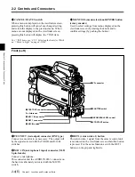
About color bar or test signal output
When performing auto-setup using a remote control
panel or master setup unit, setup may be performed
during the output of a color bar or test signal. After
setup is complete, the color bar or test signal will again
be displayed on the viewfinder screen.
For more information, refer to the System Manual.
3-2-2 Power Supply
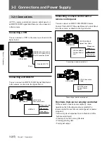
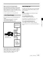
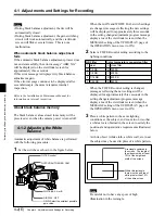
This camera operates on any of the following power
supplies.
• Power supplied from connected equipment
• Power from an AC adaptor
• Power from the attached battery pack
With the POWER switch set to CCU, the camera is
turned on when a camera control unit is connected.
With the POWER switch set to EXT, the camera is
turned on when power is supplied via the VTR
connector or the DC IN connector.
HDC-950/930
HD Color Video Camera
HDCU-900/950
Camera Control
Unit
Optical multi-
connector
VTR connector
HDCD-50
HD Signal
Distributor
DC IN
connector
• AC-550
AC Adaptor
• BKP-L551
Battery Adaptor
+ BP-L60/L80
Battery Pack
Using a battery pack
To supply power from a battery pack, set the POWER
switch to EXT and attach a battery adaptor or battery
case to the camera.
Note
The DC-L1/L90 Battery Case cannot be mounted
directly to the camera.
To use a BP-90 Battery Pack
Use a DC-300 Battery Case (optional).
For information on mounting the battery case, see the
operation manual supplied with the battery case.
To use a BP-L60/L80 Battery Pack
Use the BKP-L551 Battery Adaptor (optional).
For more information, refer to Installation & Maintenance
Manual.


