


Chapter 2 Locations and Functions of Parts
Chapter 2
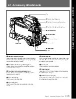
Locations and Functions of Parts
2-7(E)
7
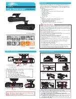
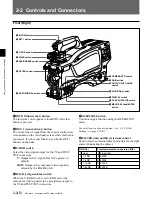
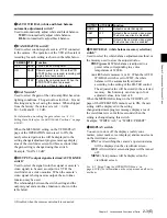
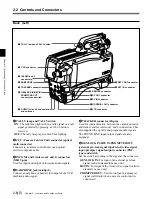
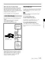
AUDIO IN (auido input 1, 2) connectors (BNC
type) and switches
Connect audio signals. An input select switch and
microphone power switch are provided for each
channel.
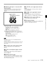
Input select switch: Set to the appropriate position
according to the connected eqiupment.
LINE: When a line-level signal source is
connected
MIC: When a microphone is connected
Microphone power switch: When a microphone is
connected, set whether or not to supply a power to
the microphone.
+48V: To supply a power of +48 V
OFF: Not to supply a power
•: To supply a power of +12 V
Note
To supply a power of +12 V, modification of the
camera is required.
For details, refer to the Installation & Maintenance Manual.
Note that the modification must be performed by a service
personel only.
8
RET CONT (return control) connector (6-pin)
Used for connection to a CAC-6 Return Video
Selector.
9
EXT I/O (external input and output) connector
(20-pin)
Used to supply signals, such as Y/Pb/Pr signals, to
external equipment.
0
REMOTE connector (8-pin)
Used for connection to an RM-B150 Remote Control
Unit, RCP-700-series Remote Control Panel or MSU-
700A/750 Master Setup Unit.
LINE MIC
OFF+48V
AUDIO
CH-1
IN
LINE MIC
OFF+48V
CH-1
Input select switches
Microphone power switches
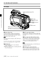
qa
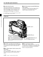
DC OUT (DC power supply output) connector
(4-pin)
Used to supply power to devices such as a wireless
receiver (optional).
qs
DC IN (DC power supply input) connector
(XLR 4-pin)
Used for connection to the AC-550/550CE AC
Adaptor, a battery etc. to supply power to the camera.
qd
HD SERIAL OUT connector (BNC type)
Used for output of HD SDI serial data.
qf
VTR connector (26-pin)
Used for connection to a VTR (such as the HDW-250)
or HDCD-50 HD Signal Distributor.