background image

23

Loading Film Sheets

  Op

er

a

tio
n

3

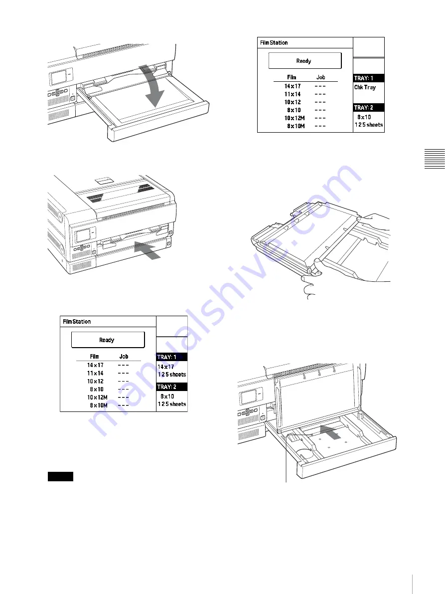
Close the film tray cover.

7

Insert film tray 1.

After a few seconds, the film tray is locked and the 
following message appears on the LCD.

To calibrate the printing density

We recommend calibrating the printing density of the 
loaded film by referring to “Calibrating the Printing 
Density” on page 32.

Notes

• Be sure to insert film tray 1 all the way into the unit 

until it stops. When the film tray is not inserted 
completely and the film sheets are not loaded 
correctly, the following message appears on the 
LCD.

• If you try to insert the film tray into the wrong film 

tray side, you cannot do so because the stopper 
prohibits you from inserting the tray all the way in.

If the cover of the film tray comes off

Remove the film tray and re-attach the cover.

When using size 8 × 10 (about 202 × 253 mm) film

Insert the film sheets securely as the printing surface 
protection sheet passes over the stopper located in the film 
tray.

Stopper

Содержание FilmStation UP-DF750

Страница 1: ...mprised of the Instructions for Use and the Setup Manual The Instructions for Use gives the information on how to use the printer for the routine work The Setup Manual gives the system administrator the information needed to setup the printer and connect it to the network UP DF750 2008 Sony Corporation ...

Страница 2: ...the interference at his own expense You are cautioned that any changes or modifications not expressly approved in this manual could void your authority to operate this equipment All interface cables used to connect peripherals must be shielded in order to comply with the limits for a digital device pursuant to Subpart B of Part 15 of FCC Rules For the customers in Canada This unit has been certifi...

Страница 3: ...the construction requirements of IEC60601 1 and providing at least Basic Insulation 5 The leakage current could increase when connected to other equipment 6 This equipment generates uses and can radiate radio frequency energy If it is not installed and used in accordance with the instruction manual it may cause interference to other equipment If this unit causes interference which can be determine...

Страница 4: ...ion in which it will be used Guidance and manufacturer s declaration electromagnetic emissions The UP DF750 is intended for use in the electromagnetic environment specified below The customer or the user of the UP DF750 should assure that it is used in such an environment Emission test Compliance Electromagnetic environment guidance RF emissions CISPR 11 Group 1 The UP DF750 uses RF energy only fo...

Страница 5: ...mode 2 kV common mode 1 kV differential mode 2 kV common mode Mains power quality should be that of a typical commercial or hospital environment Voltage dips short interruptions and voltage variations on power supply input lines IEC 61000 4 11 5 UT 95 dip in UT for 0 5 cycle 40 UT 60 dip in UT for 5 cycles 70 UT 30 dip in UT for 25 cycles 5 UT 95 dip in UT for 5 sec 5 UT 95 dip in UT for 0 5 cycle...

Страница 6: ...transmitters as determined by an electromagnetic site survey a should be less than the compliance level in each frequency range b Interference may occur in the vicinity of equipment marked with following symbol NOTE 1 At 80 MHz and 800 MHz the higher frequency range applies NOTE 2 These guidelines may not apply in all situations Electromagnetic propagation is affected by absorption and reflection ...

Страница 7: ... EC For details please access the following URL http www compliance sony de Recommended separation distances between portable and mobile RF communications equipment and the UP DF750 The UP DF750 is intended for use in an electromagnetic environment in which radiated RF disturbances are controlled The customer or the user of the UP DF750 can help prevent electromagnetic interference by maintaining ...

Страница 8: ...8 For the customers in Taiwan only ...

Страница 9: ...ion 28 Menu Operation 29 Confirming Information 29 Adjusting the Print Quality 29 Calibrating the Printing Density 32 Selecting a Gamma Curve 34 Making Network and LCD Panel Settings 35 Test Print 38 Other Settings 39 Miscellaneous Precautions 40 Safety 40 Installation 40 Transporting the Unit 40 Cleaning the Cabinet 40 Maintenance 40 Specifications 43 Messages 45 Error Messages 45 Other messages ...

Страница 10: ... You can select the type of blue thermal film from among the following standard film sizes used for modality 14 17 about 353 430 mm 11 14 about 279 355 mm 10 12 about 253 304 mm 8 10 about 202 253 mm Also the unit provides sufficient high picture quality for image diagnosis Space saving You can place the unit either horizontally or vertically This allows you to design your system configuration fre...

Страница 11: ...is button is activated when the power is on and all covers are closed G EJECT TRAY button Push this button to pull film tray 2 out This button is activated when the power is on and all covers are closed H Film output slot 1 Printed film sheets film sizes 8 10 about 202 253 mm 10 12 about 253 304 mm 11 14 about 279 355 mm are ejected here I Output tray 15 Printed film sheets film sizes 8 10 about 2...

Страница 12: ... cover 1 49 Open this cover when removing jammed film sheets loaded in film tray 1 S Rear cover 2 49 Open this cover when removing jammed film sheets loaded in film tray 2 T Network connector RJ 45 modular jack 17 Used to connect to a LAN CAUTION For safety do not connect the connector to peripheral device wiring that might have excessive voltage Follow the instructions for this port U Cable stopp...

Страница 13: ...eft digit indicates the number of the menu item selected with the cursor B The right digit indicates the total number of menu items including those that are currently not shown on the menu screen B Menu item Shows a list of menu items and the cursor B for selecting an item C Operation guidance Shows possible actions for the current menu screen Menu screen Settings screen A Menu item name Shows the...

Страница 14: ...cking materials from inside the unit and film trays 1 Open the top cover and inner cover page 50 and remove the packing materials from inside the unit 2 Pull out film tray 1 and remove the tray cover 3 Remove the packing material and place the cover back onto the tray 4 Repeat steps 2 and 3 for film tray 2 5 Place film trays 1 and 2 back into the unit Notes Failure to remove the packing materials ...

Страница 15: ... will not continue the printing operation Output tray size The combinations for film size and corresponding output tray size are as listed below Large Size This is the factory default setting Note If you use film size 11 14 about 279 355 mm while the output tray stopper is mounted a film jam will occur When the output tray is inserted completely the surface of the unit and that of the output tray ...

Страница 16: ...nit may topple and cause injury Do not use the casters for any purpose other than pulling the unit forward for maintenance If you place the unit without providing adequate space around it heat may build up inside the unit and result in fire or damage Be sure to provide at least 8 cm 3 1 4 inches of space around the unit Notes Be sure to use casters and stopper sheet sold separately when placing th...

Страница 17: ...le Turning the Unit On or Off Turn the printer power on after you connect the AC power cord Turning the main power of the unit on Set the amain POWER switch to the on side Note The unit is not turned on even if the amain POWER switch of the unit is turned on Turning the unit on Use the 1ON STANDBY switch located on the front of the unit to turn the unit on during daily use 1 Press the 1ON STANDBY ...

Страница 18: ...switch located on the front panel is set to on Turning the unit off Use the 1ON STANDBY switch located on the front of the unit to turn the unit off during daily use 1 Press the 1ON STANDBY switch to turn the unit off The 1ON STANDBY indicator blinks and goes off The message Please Wait appears on the LCD and then the message disappears The printer is turned off When you do not intend to use the p...

Страница 19: ...mography Blue Thermal Film UPT M710BL Contains 125 sheets of size 8 10 transparent blue thermal film about 202 253 mm suitable for mammography Note Be sure to use film sheets made expressly for the UP DF750 If you use other film sheets the quality of the printout cannot be guaranteed Use of another type of film sheets may also cause malfunction of the unit Loading Film Sheets About the film tray T...

Страница 20: ...d film sheets in the lower tray in the same way as you do for the upper tray Notes Hold the film using the damp proof bag Do not touch the film directly Dust finger prints or sweat are likely to cause unsatisfactory printing Hold both sides of the film tray and tray cover tightly when handling the film tray 1 Push the EJECT TRAY button for film tray 1 on the front panel Film tray 1 is partially ej...

Страница 21: ...ng surface protection sheet remains in film tray 1 remove it 3 Remove the damp proof bag from the carton 4 Open the damp proof bag by tearing at the pre cut tabs Note Remove the seal after loading the film into film tray 1 If you remove it before loading the film sheets may slip and drop Pull it upward in the direction of the arrow putting your fingers in the grooves Seal used to grasp the film sh...

Страница 22: ...t add film sheets halfway through one bag of film sheets The reason for this is because the unit counts the remaining film sheets using the IC tag on the printing protection sheet on the bottom of the pile of sheets 6 Remove the seal used to secure the film sheets in the package from the film sheets placed in the film tray 1 Remove the sticky part of the seal pulling the blank part of the seal tow...

Страница 23: ...ay into the unit until it stops When the film tray is not inserted completely and the film sheets are not loaded correctly the following message appears on the LCD If you try to insert the film tray into the wrong film tray side you cannot do so because the stopper prohibits you from inserting the tray all the way in If the cover of the film tray comes off Remove the film tray and re attach the co...

Страница 24: ...eets may move to the outlet of the film tray This may cause film jamming In such a case put the film sheets back inside the film tray by pushing them with your finger as shown below Notes on storing film sheets If you remove the film sheets and plan to keep them for a long time store unused film in the damp proof bag Store unopened packages in a cool dark place Printing Before printing Ensure that...

Страница 25: ... a case the output tray size must be changed Please contact your Sony dealer to have the size adjustment performed To prevent film jamming do not allow more than 30 printouts to remain on the film output slot when placing the unit horizontally and more than 15 printouts to remain when placing the unit vertically Depending on usage conditions the message Remove Prints may appear or the indication R...

Страница 26: ...Loading Film Sheets on page 19 The unit restarts printing when the film tray is fully inserted Note When the message Set Film or Rmv Prt appears on a row of the LCD the unit stops printing from the corresponding film tray However the unit will continue printing in the other film tray In this case printing order may change Notes on storing your printouts Do not leave the printouts in direct sunligh...

Страница 27: ...next printout will be printed with the values most recently set You cannot adjust the setting during printing Once you have adjusted and stored the settings the printer operates according to those settings until their values are modified If no button is pressed for about 20 seconds after pressing the MENU button the indication automatically returns to the standard screen However during IP address ...

Страница 28: ... Calibration Auto Calibration Calibration Reset 14x17 11x14 10x12 8x10 10x12M 8x10M Network Setting LCD Back Light LCD Brightness LCD Contrast Language Setting Position Quality Control SMPTE Total Print Gamma 1 20 Sharpness Pattern Print Select Point 95 Select Point 5 Save Gamma Gamma 1 20 Sharpness Pattern Print Select Point 95 Select Point 5 Save Gamma Preset1 Preset2 Preset3 Preset4 Preset5 Edi...

Страница 29: ...ead etc is necessary For details see Maintenance on page 40 Adjusting the Print Quality You can adjust the following items for each gamma curve The adjusted settings are stored for each blue thermal film gamma curve Sharpness of the printout You can adjust the sharpness among 17 levels between 1 and 16 including OFF Tone of printouts You can adjust the high tone dark area of the images and the low...

Страница 30: ...enters the sharpness adjustment mode 6 Select the desired level by pressing the F or f button The sharpness setting range is 1 16 or OFF The default setting is OFF Pressing the F button increases the sharpness value emphasizing the outline of the print image Pressing the f button decreases the sharpness value making the outline of the print image less distinct After the sharpness has been adjusted...

Страница 31: ...art of the low tone range 2 Display the selected number by pressing the F or f button To reset to the default setting of the low tone range Display 25 11 Press the EXEC button The low tone setting is stored and the following screen appears on the LCD panel If the screen does not appear press the G button to return to step 4 press the F or f button to move the cursor to Point5 and then press the g ...

Страница 32: ...e the menu screen and return to the standard screen Calibrating the Printing Density The unit automatically calibrates the printing density according to the density curve set Perform calibration for each type of blue thermal film separately It is recommended to perform this operation when new film was inserted 1 Press the MENU button to bring up the menu screen The next darkest part The darkest pa...

Страница 33: ...ion 4 Press the MENU button The menu screen closes and the unit returns to the standard screen To perform calibration of another blue thermal film Repeat step 1 to 3 To make an automatic calibration The unit can perform a calibration for the first film each time you load new film sheets into the film tray 1 or film tray 2 1 Press the F or f buttons to move the cursor to Auto Calibration and then p...

Страница 34: ...e default The LCD panel indication changes as follows 4 Press the MENU button The menu screen closes and the unit returns to the standard screen To reset another type of blue thermal film to the default status Repeat steps 1 to 4 Selecting a Gamma Curve If the gamma curve has not been specified at the modality side the gamma curve selected at the unit will be used for printing In this case the gam...

Страница 35: ... type selection screen 6 Repeat steps 3 6 to change the gamma curve for the remaining blue thermal film types 7 Press the MENU button The menu screen closes and the unit returns to the standard screen Making Network and LCD Panel Settings This section explains how to make network settings and how to adjust various LCD panel settings including backlight operation brightness contrast display languag...

Страница 36: ...utton to move the cursor to the desired setting LCD Brightness A value indicating the current LCD panel brightness setting is shown on the menu screen The brightness setting range is 1 20 Pressing the F button increases the value and makes the LCD panel brighter Pressing the f button decreases the value and makes the LCD panel darker LCD Contrast A value indicating the current LCD panel contrast s...

Страница 37: ...orientation and key layout Changing the LCD panel orientation also will change the key layout as shown below Vertical R Vertical L 4 When the setting is complete press the MENU button The menu screen closes and the unit returns to the standard screen Setting Description Horizontal Standard horizontal orientation Factory default setting Vertical R Display is rotated counterclockwise by 90 degrees f...

Страница 38: ...selecting the pattern appears 3 Press the F or f button to move the cursor to the pattern that you want to print and press the g button Quality Control Print quality checking pattern This pattern can only be printed on UPT M710BL M712BL film SMPTE Test image pattern A screen for starting to print the selected pattern appears 4 Press the F or f button to move the cursor to the film size that you wa...

Страница 39: ...e changed but not by using the menu However you cannot change the following settings by yourself To change the following settings contact your Sony dealer Item Default setting Making the buzzer sound when error messages such as Set Film Remove Prints and so on are displayed Off No buzzer Reversing the printouts horizontally Off Do not reverse the printouts Attaching the L and R marks on each print...

Страница 40: ...turn off the power and allow the printer to stand for at least one hour If the film is subjected to wide and sudden changes in temperature condensation may form on the film in the film tray This will cause the printer to malfunction Also if the film is used in this state spots are likely to appear on the printout To store a half used package of film replace the film in its original packing and res...

Страница 41: ...ng film on the new cleaning roller and attach the new cleaning roller Notes Be careful not to scratch the surface of the cleaning roller and not to drop it Do not wipe the surface of the cleaning roller with the supplied cleaning sheet 4 Close the front cover completely If you continue with the cleaning of the thermal head it is not necessary to close the front cover Go to step 2 of Cleaning the t...

Страница 42: ...filters Ventilation holes are provided on the unit to prevent it from overheating Three filters are provided on the front cover for covering the ventilation holes To clean the filters proceed as follows 1 Pull the front cover lock lever to open the front cover 2 Lift one of the filters upward a little and pull it toward you to remove it Do the same with the others 3 Clean the filters using a vacuu...

Страница 43: ...6 mm w h d 23 5 8 12 1 2 27 1 8 inches Without including projecting parts Mass Approx 65 kg 143 lb 4 oz Printing system Thermal printing Resolution 23 78 dot mm 604 dpi Gradations 16 384 levels processing Maximum print size 346 7 415 3 mm when using the UPT 517BL Picture elements 8 256 9 888 dots w h when using the UPT 517BL Throughput Approx 75 sheets hour excluding the time for cooling the head ...

Страница 44: ...ons of the Directive 1999 5 EC For details please access the following URL http www compliance sony de Precautions Store unopened film in a cool dark place Open film only when ready to use Please refer to the imager s instruction manual about how to load the film Prompty load the film into the tray and place into the imager This film is specifically designed for Sony imagers Do not use with imager...

Страница 45: ...your Sony dealer Remove FilmXXXXXX 1 Film has jammed at the location indicated by XXXXXX Refer to the illustration shown on the LCD panel and remove the jammed film Error Please Power OFF Power ON Again Internal system of printer could not be started tPress the 1 ON STANDBY switch to turn power off and then turn power on again by pressing the 1 ON STANDBY switch once more Set Tray The required fil...

Страница 46: ...rs During continuous printing operation will resume when the head has cooled down and the message disappears Head Cooling Please Wait The thermal head is currently being warmed up tWait until the message disappears Printing will start when the head has been warmed up and the message disappears Head Heating Please Wait The printer is performing an internal processing operation such as when the film...

Страница 47: ... film tray and the tray cover with both hands Symptom Possible causes and remedies Nothing appears on the LCD The 1ON STANDBY switch on the front panel of the unit is not pressed tPress the 1ON STANDBY switch to turn the unit on Page 17 The connections may not be correct tMake the connections correctly Page 17 The unit has not turned on even though the 1ON STANDBY switch on the front panel is pres...

Страница 48: ...se the removed film Discard it 3 Re insert the film tray as it was When placing the unit vertically Pay attentions to the following points when you remove or insert the film tray with the unit placed vertically Do not give a shock to the film tray Doing so may cause the film sheets will move inside the film tray This may result in the film jamming When removing or inserting the film tray hold it b...

Страница 49: ...h hands When rear cover 1 is opened When rear cover 2 is opened Note When you have to open rear cover 1 and rear cover 2 at the same time open the rear covers open rear cover 2 first and then rear cover 1 When you close the rear covers close rear cover 1 first and then rear cover 2 When the top cover is opened When the front cover is opened When the top cover and front cover are opened ...

Страница 50: ...s To remove film jammed in the output tray 1 Remove the output tray completely 2 Remove the jammed film near the inside of the unit 3 Re insert the output tray as it was Note Be sure to inert the output tray completely For detailed information on how to insert the output tray completely see page 15 To remove film jammed in multiple locations Open all of the covers rear front top and inner covers a...

Страница 51: ...lowing describes how to print the quality control pattern the configuration of the quality control pattern and how to carry out the actual evaluation of each item Procedure for Printing Quality Control Pattern Notes Before you print the quality control pattern turn on the power of the printer a minimum of at least 15 minutes beforehand A quality control pattern can only be printed on UPT M710BL an...

Страница 52: ...x Step 2 High density HD Step 3 Medium density MD Step 4 Low density LD Step 5 Minimum density Dmin There is a field for entering the density of each step and a field for entering the difference density DD value obtained by subtracting the density of step 4 from that of step 2 In this area enter each of the density values displayed on the LCD of the printer after you print the quality control patt...

Страница 53: ...n and basis value fall within the density tolerance range s Does the difference between the density value of density step 3 MD and basis value fall within the density tolerance range s Does the difference between the density value of density steps 2 4 DD and basis value fall within the density tolerance range Measures If the density values are out of the density tolerance ranges implement the corr...

Страница 54: ... Frequency Weekly Evaluation Procedure 1 Print the quality control pattern page 51 2 Check the extremely low and high gradient check area Check Points s Is there a difference visually between the dark frame surrounding the background of the three white squares and the black background of the quality control pattern s Is there a difference visually between the background of the three black squares ...

Страница 55: ... still no improvement after performing 2 above consult your Sony dealer Aspect Check Check Frequency Yearly Check Procedure 1 Print the quality control pattern page 51 2 Check that the lines of the aspect check area are printed straight and measure the length of the horizontal line HL and vertical line VL either left or right Check the aspect from the lengths of these two lines Check Point s Does ...

Страница 56: ...56 Mammography Quality Control Guide Miscellaneous ...

Страница 57: ...g the cleaning roller 41 Menu Calibration 33 Configuration 28 Default Gamma 34 Information 29 System Settings 36 Test Print 38 Menu operation calibrating the printing density 32 confirming information 29 LCD panel settings 35 making network 35 selecting a gamma curve 34 test print 38 Messages error messages 45 other messages 46 O Output tray 15 P Placing the unit vertically 16 Power turning on the...

Страница 58: ...Manual Table of Contents Overview Contents of This Document 59 Setup About the IP Address 60 Checking the IP Address 60 Setting the IP Address 60 Completion Check 64 Network Setup Screen Transition Diagram 65 ...

Страница 59: ...administrators about the topics listed below including the setup procedure for connecting the UP DF750 subsequently called the unit to a network The Setup Manual consists of the following parts Setup Explains how to specify the IP address and perform other setup steps that are necessary for connecting the unit to a network ...

Страница 60: ...g the IP Address To confirm the IP address perform the following steps 1 Turn the UP DF750 on 2 Press the MENU button The menu screen appears 3 Use the F and f buttons to move the cursor to Information and press the g button The current IP address setting is shown Setting the IP Address To assign an IP address to be used by the unit perform the following steps Note If network settings are changed ...

Страница 61: ...tup for a period of about 30 minutes the unit reverts to the standard screen Any settings that were made up to that point will be lost To edit a preset and use the result as network settings 1 Use the F and f buttons to move the cursor to Edit and press the g button The Edit Preset screen appears 2 Press the g button A screen for selecting the Preset Preset 1 5 or Temporary appears Settings made a...

Страница 62: ...and 8 to make the Subnet Mask and Default Gateway settings After the Default Gateway setting has been confirmed by pressing the EXEC button the AE Title screen appears 10 Set the AE title Use the F and f buttons to change the character under the cursor Use the G and g buttons to move the cursor Note You can specify any character string such as SONY as AE title but once the string has been set a pr...

Страница 63: ...network settings may take a few minutes To call up a preset and use the result as network settings 1 Use the F and f buttons to move the cursor to the number of the Preset to use and press the g button In this example Preset 2 is selected The current settings of Preset 2 are shown 2 Use the F and f buttons to move the cursor to Save Settings and press the g button The Save Settings screen appears ...

Страница 64: ...n power to the UP DF750 on 3 Mount a tray with blue thermal film loaded 4 Send image data from the modality If the unit has been set up correctly printing starts If printing does not start the image data have not reached the printer This means that the network settings are incorrect Check the IP address and other network settings of the unit and also verify that the correct settings are being used...

Страница 65: ...65 Setting the IP Address Setup Network Setup Screen Transition Diagram This diagram shows the overall flow of the network setup procedure Use it when wishing to return to earlier screens etc ...

Страница 66: ...Sony Corporation ...

Отзывы: