


6-15
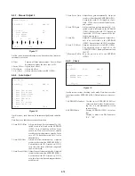
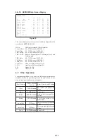
6-6-10. EEPROM Data Screen Display
EEPROM data
CD
DVD
ID No.
00
SL
L0
L1
Focus Offset
80
80
80
80
Focus Gain
30
18
30
30
TRK Offset
80
80
80
80
TRK. CONT.
??
??
??
??
TRK Gain
30
30
30
30
Tilt Offset
80
80
80
80
Pullin Level
9e
9f
ab
ab
EQ. Boost
??
??
??
??
L.F.O
??
??
??
??
SD. ?? HY. ??
Figure 20
This screen displays various set values including adjusted results
stored in the EEPROM (IC801).
ID No.
: Nothing is displayed (00 is displayed)
Focus Offset : 00 – FF 80 center (DVD_SL)
Focus Gain
: 00 – 7F 20 center (DVD_SL)
TRK. Offset : 00 – FF 80 center (DVD_SL)
TRK. CONT. : Refer to Manual adjust 1 Tracking offset 2 and
Tracking gain.
TRK. Gain
: 00 – 7F 20 center (DVD_SL)
Tilt Offset
: 00 – FF 80 center (DVD_SL)
Pullin Level : 80 – FF D0 center (DVD_SL)
EQ. Boost
: Fixed according to the disc type.
L.F.O
: Only lower 5 bits are effective.
SD.
: About 50 – E0
HY.
: About 60 – A0
6-7. Other Operation
For manual operation of the drive, the following operations are
available, besides the operations given on the menu screen. (Com-
mon to front panel and remote commander)
Eject/Loading
OPEN/CLOSE
Stop+Ejection, and Loading
button
Clear
CLEAR button
Movement throughout the
menu
Stop
STOP button
Servo stop
Retrun
RETURN button
Return to drive manual op-
eration
Set up
SET UP button
STOP, then return to test
mode menu
Cursol key
→↑
keys
Increase manually adjusted
value
Cursol key
←↓
keys
Decrease manually adjusted
value
Power
POWER button
Power OFF
Содержание DVP-S7700
Страница 11: ...1 1 SECTION 1 GENERAL DVP S7700 This section is extracted from AEP UK model instruction manual 3 864 941 31 ...
Страница 12: ...1 2 ...
Страница 13: ...1 3 ...
Страница 14: ...1 4 ...
Страница 15: ...1 5 ...
Страница 16: ...1 6 ...
Страница 17: ...1 7 ...
Страница 18: ...1 8 ...
Страница 19: ...1 9 ...
Страница 20: ...1 10 ...
Страница 21: ...1 11 1 11 E ...
Страница 36: ...DVP S7700 4 3 4 4 4 1 FRAME SCHEMATIC DIAGRAM 1 2 FRAME 1 2 ...
Страница 37: ...DVP S7700 4 5 4 6 FRAME SCHEMATIC DIAGRAM 2 2 FRAME 2 2 ...
Страница 39: ...DVP S7700 4 9 RF SERVO TK 47 DVP S7700 1 669 298 05 13 13 TK 47 BOARD SIDE B A B C D E F G H 1 2 3 4 5 6 ...
Страница 41: ...DVP S7700 4 13 4 14 TK 47 RF SERVO 2 SCHEMATIC DIAGRAM Ref No TK 47 board 3 000 series RF SERVO 2 TK 47 2 2 ...
Страница 71: ...DVP S7700 4 73 4 74 FP 75 FL DRIVER SCHEMATIC DIAGRAM Ref No FP 75 board 1 000 series FL DRIVER FP 75 ...